HOW TO: Check Fuel Relay with Multimeter
 Sep 7, 2009, 12:23 PM
#1
HOW TO: Check Fuel Relay with Multimeter
Since there has been a bit of confusion on how to check the fuel relay that people are having issues with, I decided to make a mini write up.
Items Required:
Multimeter
About 2-4ft. of wire red/black
Fuel Relay
A Brain
Beer
1.)Locate the Fuel Pump Relay

2.)Pull out Fuel Pump Relay
3.)Connect Red Wire to (+) and Black Wire to (-). I chose to use the RED for the 12v and the jump start terminal in the engine bay, the engine as the ground.
Perform this test for continuity or if the current flows through the relay.

NOTE: Note that while the probes are not touching anything, the multimeter will indicate a reading of infinity (OL). A reading of infinity means that the circuit is open. When you touch the two probes together, the reading changes to zero. A reading of zero indicates that the circuit is closed or complete. A complete circuit is one that can conduct electricity; an open circuit cannot.
Check if the relay is any good. It says for headlights, but it works the same for the fuel pump relay since all the relays are the same part.
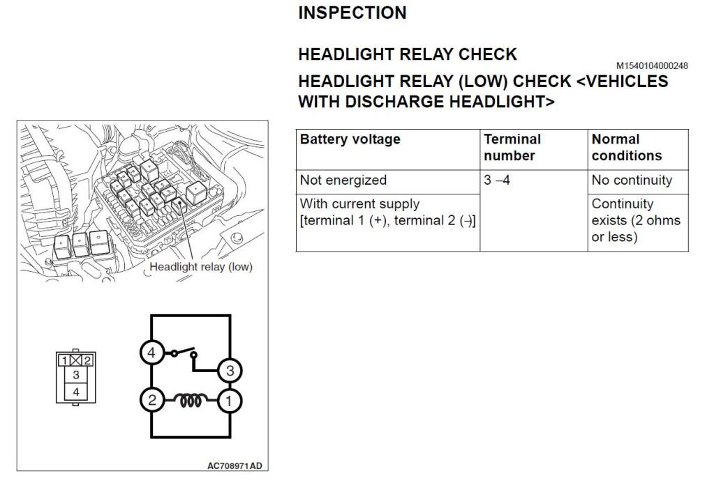
When I had current applied, I read 0.00 OHM, meaning that I had continuity and current flowed. Then when I checked relay it read less than two OHMs.
Hope this helps people. It literally took me 10 minutes to check mine.
Items Required:
Multimeter
About 2-4ft. of wire red/black
Fuel Relay
A Brain
Beer
1.)Locate the Fuel Pump Relay
2.)Pull out Fuel Pump Relay
3.)Connect Red Wire to (+) and Black Wire to (-). I chose to use the RED for the 12v and the jump start terminal in the engine bay, the engine as the ground.
Perform this test for continuity or if the current flows through the relay.
NOTE: Note that while the probes are not touching anything, the multimeter will indicate a reading of infinity (OL). A reading of infinity means that the circuit is open. When you touch the two probes together, the reading changes to zero. A reading of zero indicates that the circuit is closed or complete. A complete circuit is one that can conduct electricity; an open circuit cannot.
Check if the relay is any good. It says for headlights, but it works the same for the fuel pump relay since all the relays are the same part.
When I had current applied, I read 0.00 OHM, meaning that I had continuity and current flowed. Then when I checked relay it read less than two OHMs.
Hope this helps people. It literally took me 10 minutes to check mine.
 Sep 7, 2009, 03:46 PM
#2
Evolving Member
Join Date: Apr 2009
Location: Italy
Posts: 195
Likes: 0
Received 0 Likes
on
0 Posts
I want to specify that when you check continuity between pins 1 and 2, the resistance there should be 142 Ohm (tolerance: 10%), as you can read from the relay NAIS ACV31212 datasheet here: http://www.datasheetarchive.com/pdf-...DSA-104509.pdf
Bye
Bye
Last edited by therocket; Sep 7, 2009 at 03:56 PM.
Sep 7, 2009, 06:03 PM
#3
I want to specify that when you check continuity between pins 1 and 2, the resistance there should be 142 Ohm (tolerance: 10%), as you can read from the relay NAIS ACV31212 datasheet here: http://www.datasheetarchive.com/pdf-...DSA-104509.pdf
Bye
Bye
 Jan 3, 2010, 02:41 PM
#5
Evolving Member
Join Date: Apr 2009
Location: Italy
Posts: 195
Likes: 0
Received 0 Likes
on
0 Posts
I want to specify that when you check continuity between pins 1 and 2, the resistance there should be 142 Ohm (tolerance: 10%), as you can read from the relay NAIS ACV31212 datasheet here: http://www.datasheetarchive.com/pdf-...DSA-104509.pdf
Bye
Bye
On NEW (green) relay I don't know what is the nominal resistance between pins 1 and 2, but probably it's something around 150 Ohm.
In any case, the most important thing to check is that you have continuity (< 2 Ohm) between pins 3 and 4 when you supply +12V between pins 1 and 2
Jul 29, 2014, 02:25 PM
#7
Evolved Member
Anyone care to provide more experience with this testing method?
I just tested mine after suspecting a bad relay causing 2 blown sparkplugs in my #4 cylinder in the same weekend at the track. all relays showed >2 ohms when supplied with a 12v source. I even tested with a new black relay. New blacks show 89 ohms across 1-2 and the greens show 128 ohms. Since this test proved inconclusive for my problem, i put in brand new relays anyways and upgraded my fuel pump to a dw65. Hopefully i never have this issue again.
I just tested mine after suspecting a bad relay causing 2 blown sparkplugs in my #4 cylinder in the same weekend at the track. all relays showed >2 ohms when supplied with a 12v source. I even tested with a new black relay. New blacks show 89 ohms across 1-2 and the greens show 128 ohms. Since this test proved inconclusive for my problem, i put in brand new relays anyways and upgraded my fuel pump to a dw65. Hopefully i never have this issue again.
Last edited by hispanicpanic; Jul 29, 2014 at 02:27 PM.
Trending Topics


Thread
Thread Starter
Forum
Replies
Last Post
Clipse3GT
Evo X Engine / Turbo / Drivetrain
44
Jan 29, 2022 09:54 PM
Raptord
Evo How Tos / Installations
12
Jan 8, 2021 07:41 AM
Pal215
Evo Engine / Turbo / Drivetrain
18
Jun 11, 2017 09:47 PM