Navi Audio and Video In?
 Jul 6, 2011, 06:33 PM
#1
Newbie
Thread Starter

Join Date: Dec 2007
Location: Socal
Posts: 34
Likes: 0
Received 0 Likes
on
0 Posts
Navi Audio and Video In?
I remember reading that the oem navi supports both audio AND VIDEO in. Is this true for all years or just the 2011 navi? Also, what type of wire does it use to do the video in?
I also read on someones post that some people were getting it audio in but not video in and that it was due to having the dealer install the navi in a evo X that didnt already have the navi installed. So only the evo's that come with navi already installed are the ones that have video in?
I also read on someones post that some people were getting it audio in but not video in and that it was due to having the dealer install the navi in a evo X that didnt already have the navi installed. So only the evo's that come with navi already installed are the ones that have video in?
 Jul 7, 2011, 05:19 AM
#2
Newbie
iTrader: (1)

Join Date: Sep 2010
Location: Great White
Posts: 29
Likes: 0
Received 0 Likes
on
0 Posts
Mine came with navi from factory, it has video in, which is via the old school "yellow " cable (remember vhs?) Making it rather obsolete nowadays and on arrival (2008). It doesn't even have 3.5 for audio, it uses the red and white rca cables, but at least with those adapters are readily and cheaply available. rather dated inputs ...like a tape deck on an 04....sigh

 Jul 8, 2011, 08:17 PM
#6
Newbie
Thread Starter
Join Date: Dec 2007
Location: Socal
Posts: 34
Likes: 0
Received 0 Likes
on
0 Posts
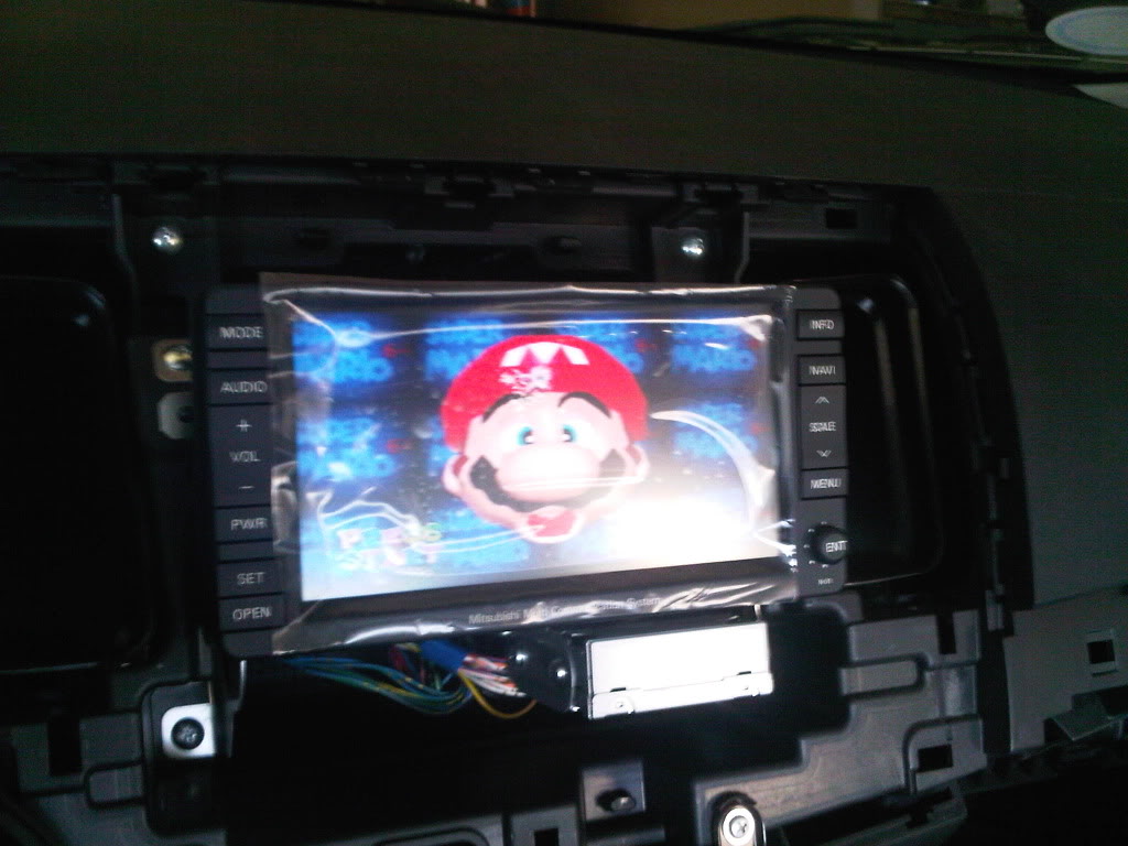
^lol mario64 nice. havent seen that in a long time.
can you replace the red and white connector with the red yellow and white connector without taking the head unit panels off? isnt it just where the cup holders are? sorry i forgot where the stock location is
can you replace the red and white connector with the red yellow and white connector without taking the head unit panels off? isnt it just where the cup holders are? sorry i forgot where the stock location is
Jul 8, 2011, 10:16 PM
#7
Yeah it pops out, its just a little box that's clipped in, you don't have to take the head unit out (those pics were of when I was installing it). You can get another chip board with the connection on it from Mitsubishi but for like 8 dollars you can do it yourself. If you guys need to know how to do it, let me know and ill post a small instruction 
Trending Topics
Jul 9, 2011, 06:25 AM
#8
Eventually, I'd like to swap out mine to the 3-RCA version and wire it up to an aftermarket 2-din nav. Easiest way to remove the box, and maybe even a picture showing how the connections are on the back would be really helpful, thanks!


 Jul 10, 2011, 07:20 AM
#10
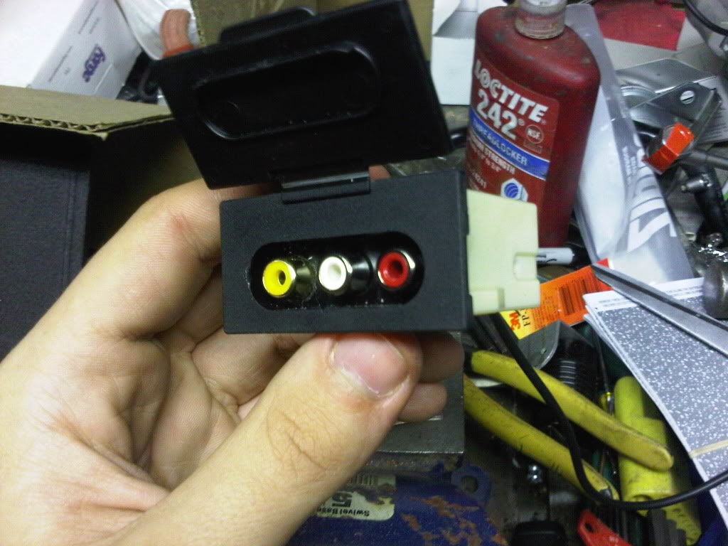
That's the beautiful thing, it doesn't hook up in the back. The AUX box that is in my hands in the picture has a harness going to it for audio hookups, all you have to do is remove the harness (it just unplugs) take out the electrical board, and solder in a yellow connection to the open slot on the board. Then you have to solder two more wires for the harness to hook up to on the back of the board, I just used paperclips for all of it and it works great.
Jul 10, 2011, 08:14 AM
#11
Evolving Member
iTrader: (6)

Join Date: Apr 2010
Location: VA
Posts: 234
Likes: 0
Received 0 Likes
on
0 Posts
That's the beautiful thing, it doesn't hook up in the back. The AUX box that is in my hands in the picture has a harness going to it for audio hookups, all you have to do is remove the harness (it just unplugs) take out the electrical board, and solder in a yellow connection to the open slot on the board. Then you have to solder two more wires for the harness to hook up to on the back of the board, I just used paperclips for all of it and it works great.
Jul 10, 2011, 01:29 PM
#12
+1 on pictures of the back.. also, myself and the others are looking to accomplish two slightly different setups with this info.. thanks again!
Jul 13, 2011, 10:18 PM
#15
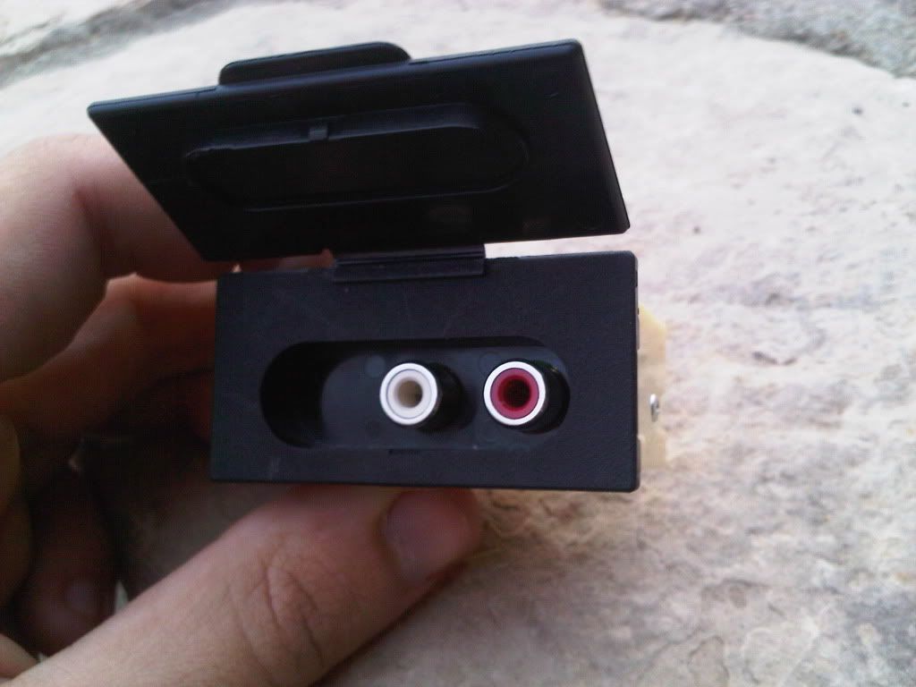
Okay, so the Aux box is clipped in with two clips on the sides, I got at it by sticking my hand through the dash (no mmcs at the time, during installation), you can see this in the second picture I posted. Unscrew the two tiny screws on the side of the box to get at the electrical board. You will need to drill a hole in the front of the box to allow the female connector to come out. Now, for the board, you're going to find something very similar to this except the leads will be soldered to the board:

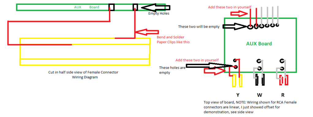
See how there are two hookups at each RCA input above? You are going to need to add both of those in by soldering to the Input itself, see here, it's the part you will need to buy, just a simple video female connector:

You have to solder one lead on the outside of the female connector, and one lead on the inside of the connector.
Once that is done, all you have to do is solder those leads to the empty holes (meant for the video lead) onto the board itself, the outside goes to the front hole and the inside goes to the back if I'm not mistaken (can't remember 100%).
Now that those are soldered, you're going to have to add two more pins to the back of the board so that the harness can read your newly found connection, simply solder two more leads beside the four that are already there in the empty holes. Make sure they're straight and thin enough so that the harness can still hook up to it, I used paper clips for the entire project.
For the best idea of what I'm trying to see, refer to my amazing paint skills below:
After the install is done, it's a good idea to wrap the connection in electrical tape or something similar so it's nicely insulated.
Let me know if you guys have any further questions, I don't think I'm forgetting anything .
.
See how there are two hookups at each RCA input above? You are going to need to add both of those in by soldering to the Input itself, see here, it's the part you will need to buy, just a simple video female connector:
You have to solder one lead on the outside of the female connector, and one lead on the inside of the connector.
Once that is done, all you have to do is solder those leads to the empty holes (meant for the video lead) onto the board itself, the outside goes to the front hole and the inside goes to the back if I'm not mistaken (can't remember 100%).
Now that those are soldered, you're going to have to add two more pins to the back of the board so that the harness can read your newly found connection, simply solder two more leads beside the four that are already there in the empty holes. Make sure they're straight and thin enough so that the harness can still hook up to it, I used paper clips for the entire project.
For the best idea of what I'm trying to see, refer to my amazing paint skills below:
After the install is done, it's a good idea to wrap the connection in electrical tape or something similar so it's nicely insulated
. Let me know if you guys have any further questions, I don't think I'm forgetting anything
.

