Knock control - load vs RPM table found
 Nov 19, 2008, 03:20 PM
#1
Evolved Member
Thread Starter

Knock control - load vs RPM table found
Through disassembly, I found that the knock control uses a present value * gain / average value.
The gain is selected from the state of a flag, which is switched from low to high gain by the attached RPM vs load table.
This fits with a false knocking car whose knock went from 0 to 36 as this map interpolated between 2000 and 2500 RPM.
I think by raising the load thresholds by RPM that you can get rid of false knock.
It is late and I have a major audit tomorrow checking work responsible for a third of my annual profits for my business. Luckily I am well prepared for it, but I must get some sleep before I can post more specifics in 24 hours. Sorry to tease!


Trending Topics
Nov 19, 2008, 06:34 PM
#8
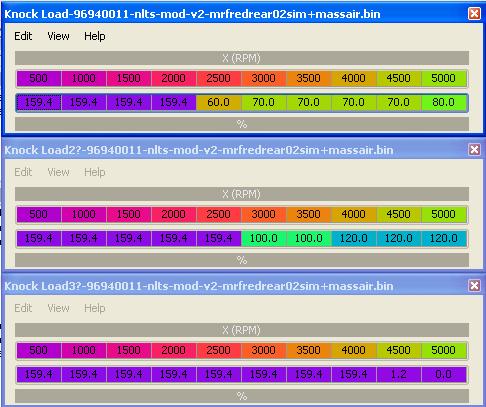
John, when you do get a chance to give the specifics....I noticed in my ROM, there are two tables directly following the one I found, same size, I think same reference to RPM and have different data values. Are these also for the same use?
Here is what I mean. Am I just being retarded and trying to define tables that shouldn't be?
Here is what I mean. Am I just being retarded and trying to define tables that shouldn't be?
Last edited by l2r99gst; Nov 19, 2008 at 06:41 PM.
Nov 20, 2008, 08:28 AM
#9
Evolved Member
Thread Starter
Yes there are a few other tables nearby that set other flags in the same variable. Needs further confirmation but I think they are to do with testing for errors in the knock sensor. The one I showed and the first one you found switch the multiplier which I think is key to knock sensitivity from the way the code flows and from how I see false knocking cars fit exactly with how you would expect them to interpolating this table.
 Nov 20, 2008, 02:45 PM
#11
Evolved Member
Thread Starter
Eric, the second table you show is the load required at each RPM to allow the octane number to be updated. Whilst it is nice to know it is there, I don't think it will be as useful as the first table that will effectively control the RPM/load where knock control operates. False knockers need to test.
Thanks MR Turco, audit went well.
Thanks MR Turco, audit went well.
Last edited by jcsbanks; Nov 20, 2008 at 02:48 PM.
Nov 20, 2008, 02:50 PM
#12
Thanks, I updated my XML.
I'm guessing the 3rd table probably isn't even load, since the last two values of 1.2 and 0.0 probably wouldn't make too much sense.
These three tables, at least in my ROM were in succession, so I mapped them all the same, thinking they may be related.
I'm guessing the 3rd table probably isn't even load, since the last two values of 1.2 and 0.0 probably wouldn't make too much sense.
These three tables, at least in my ROM were in succession, so I mapped them all the same, thinking they may be related.
Nov 20, 2008, 02:57 PM
#13
Evolved Member
Thread Starter
On mine the structure of the 3rd table suggests it is something different.
Timer interrupt results in the reading of knock ADC, goes through filter Bez has described here http://www.aktivematrix.com/forum/viewtopic.php?t=173 - I think the funny shape may not be important if only the right hand side part is used.
The bit I'm working on is the processing after that, of which this load vs RPM table is one of the crucial switches.
Nov 20, 2008, 02:59 PM
#14
The forumla that you mentioned, present value * gain / average value.....is there a specific hard coded value for the low gain and the high gain?
The table, as you mentioned, controls the switch from this low gain to high gain, thus potentially causing a higher knock count/retard once the switch to the high gain occurs, correct?
So, are these gain values defined, also, or are those calculated and changing as well?
Eric
The table, as you mentioned, controls the switch from this low gain to high gain, thus potentially causing a higher knock count/retard once the switch to the high gain occurs, correct?
So, are these gain values defined, also, or are those calculated and changing as well?
Eric

