HOW TO - Control boost using ECUFLash and the stock boost solenoid
 Oct 3, 2006, 01:42 PM
#1
HOW TO - Control boost using ECUFLash and the stock boost solenoid
This how-to will make it so you can run anywhere from wastegate boost (12-14lbs) to race gas boost (25+lbs).
DISCLAIMER
This mod will change boost charateriscs drasticallly. Do at your own risk.
You will need:
Tools
3/8 rachet
10mm socket
phillips screwdriver
regular (flat) screwdriver
regular pliars
needle nose pliars
hack saw/power wire cutters
From the store(s):
5/32 (4mm) vaccum hose (1 ft)
3/16 aluminum rod (1 ft)
one or more of the following drill bits (more on this later)
Wire gauge size drill bits.
#60 / 0.0400in. / 1.02mm
#57 / 0.0430in. / 1.09mm
Step 1
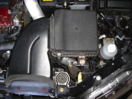
Remove the two (2) clips holding the ram air duct on.
Step 2
Undo four (4) clamps holding air box lid on. Remover lid and air filter.
Step 3
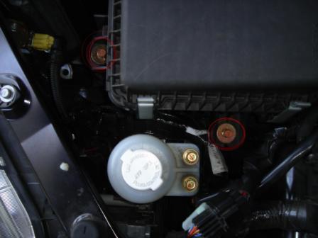
Remove two (2) 100mm bolts that sercure the air box.
Step 4
Loosen the clamp where the intake tube meets the air box.
Step 5
Remove the air box, unpluging the MAF sensor plug and unclipping the wire holder in the process.

DISCLAIMER
This mod will change boost charateriscs drasticallly. Do at your own risk.
You will need:
Tools
3/8 rachet
10mm socket
phillips screwdriver
regular (flat) screwdriver
regular pliars
needle nose pliars
hack saw/power wire cutters
From the store(s):
5/32 (4mm) vaccum hose (1 ft)
3/16 aluminum rod (1 ft)
one or more of the following drill bits (more on this later)
Wire gauge size drill bits.
#60 / 0.0400in. / 1.02mm
#57 / 0.0430in. / 1.09mm
Step 1
Remove the two (2) clips holding the ram air duct on.
Step 2
Undo four (4) clamps holding air box lid on. Remover lid and air filter.
Step 3
Remove two (2) 100mm bolts that sercure the air box.
Step 4
Loosen the clamp where the intake tube meets the air box.
Step 5
Remove the air box, unpluging the MAF sensor plug and unclipping the wire holder in the process.
Last edited by Evo_Jay; Nov 25, 2009 at 06:35 AM.
 Oct 3, 2006, 01:53 PM
#2
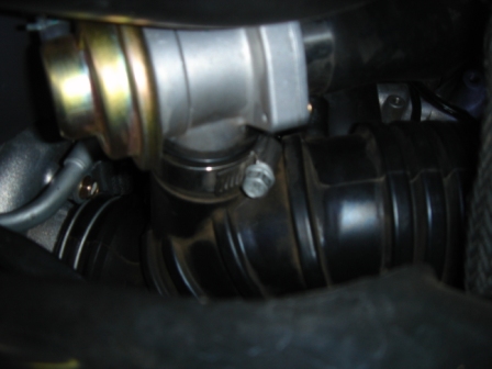
Step 6
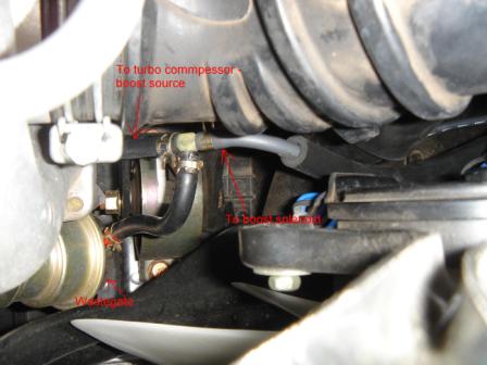
Take a look at the boost lines and get familar with the configuration.

Step 7
Loosen DV/BOV
Step 8
Remove breather hose near DV/BV (behind it).
Step 9
Loosen the clamp where the intake tube meets the turbo
Step 10
Remove intake tube, disconnecting the vaccum hose from the boost solenoid in the process.
Step 11
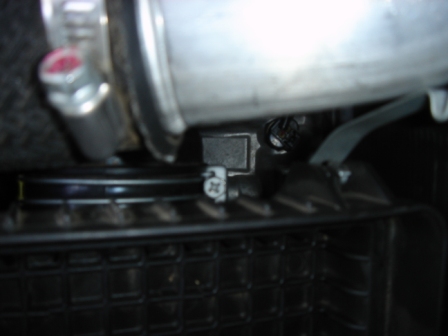
Using the needle nose pliars, pinch the clamp holding the vaccum line going to the turbo outlet pipe (at the turbo outlet pipe, not the tee) and slid the clamp up the line, then pull the line off.
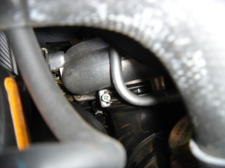
Step 12
Using the regular pliars, pinch the clamp holding the vaccum line going to the wastegate (at the tee, not at the wastegate) and slid the clamp up the line, then pull the line off.
Step 13
Take the short line going from the tee to the turbo off the tee.

Take a look at the boost lines and get familar with the configuration.
Step 7
Loosen DV/BOV
Step 8
Remove breather hose near DV/BV (behind it).
Step 9
Loosen the clamp where the intake tube meets the turbo
Step 10
Remove intake tube, disconnecting the vaccum hose from the boost solenoid in the process.
Step 11
Using the needle nose pliars, pinch the clamp holding the vaccum line going to the turbo outlet pipe (at the turbo outlet pipe, not the tee) and slid the clamp up the line, then pull the line off.
Step 12
Using the regular pliars, pinch the clamp holding the vaccum line going to the wastegate (at the tee, not at the wastegate) and slid the clamp up the line, then pull the line off.
Step 13
Take the short line going from the tee to the turbo off the tee.
Last edited by Evo_Jay; Nov 25, 2009 at 06:43 AM.
Oct 3, 2006, 02:06 PM
#3
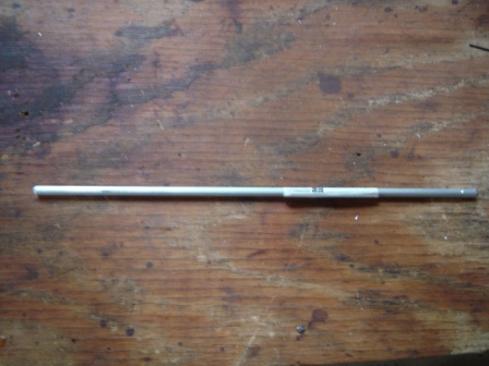
Step 14
Take the aluminum rod and cut off a 5/16in (8mm) section.
Step 15
Now for the drill bit selection.
If you just want to make enough head room for pump gas boost (20-23lbs), use the #57 drill bit.
If you want to be able to run pump gas boost and race gas boost (25+lbs), use the #60 drill bit.
You can also experiment with other sizes. Just remember that the high # of the drill bit means a smaller hole, and in turn, higher boost.
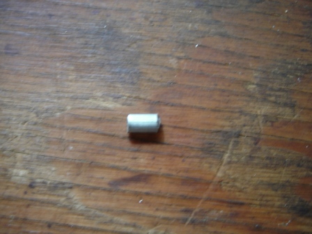
Step 16
Using a vise to hold it, drill a hole though the small section of aluminum rod. Try and get the hole as strait and center as you can.
Step 17
Cut a piece of the vaccum line about the same lenght of the stock piece. Using a 3mm allen wrench (or similar item), push the newly drilled small section of aluminum rod into the vacuum line, to the middle.
Step 18
Using the new vaccum line and modified pill to replace the stock piece going from the tee to the turbo outlet pipe, put everything back together and go get your laptop and Tactrix cable.
Take the aluminum rod and cut off a 5/16in (8mm) section.
Step 15
Now for the drill bit selection.
If you just want to make enough head room for pump gas boost (20-23lbs), use the #57 drill bit.
If you want to be able to run pump gas boost and race gas boost (25+lbs), use the #60 drill bit.
You can also experiment with other sizes. Just remember that the high # of the drill bit means a smaller hole, and in turn, higher boost.
Step 16
Using a vise to hold it, drill a hole though the small section of aluminum rod. Try and get the hole as strait and center as you can.
Step 17
Cut a piece of the vaccum line about the same lenght of the stock piece. Using a 3mm allen wrench (or similar item), push the newly drilled small section of aluminum rod into the vacuum line, to the middle.
Step 18
Using the new vaccum line and modified pill to replace the stock piece going from the tee to the turbo outlet pipe, put everything back together and go get your laptop and Tactrix cable.
Last edited by Evo_Jay; Mar 1, 2022 at 02:09 PM.
Oct 3, 2006, 02:21 PM
#4
DONT DRIVE UNTIL YOU HAVE ATLEAST LOWERED THE WGDC TO 50
Step 19 - Tuning
The following maps will need to be changed for basic boost control
Max WGDG/Basline WGDC (NOTE: map will be titled MAX WGDC or Baseline WGDC, based on what definitions your using. They are the same map.)
Boost Desired Engine Load
Boost Control Load Offset
Turbo Boost Error Correction
Boost Limit - This is the famous "Boost/fuel Cut". Set this about 20 higher then your max load.
PROCESS
***When taking the car out for the first test drive, roll on to boost SLOWLY and constantly monitor boost. If it starts to boost more then a safe amount for your octane and tune, LET OFF THE GAS.
Zero out the right side of the "Turbo Boost Error Correction" map. (keep a copy of the stock settings somewhere)
Then use the "Max WGDG/Basline WGDC" to get your desired boost curve in 3rd gear.
**Here is an example
RPM - WG duty
2000 - 70
2500 - 60
3000 - 50
3500 - 50
4000 - 50
4500 - 50
5000 - 55
5500 - 55
6000 - 60
6500 - 65
7000 - 70
After you have your desired boost curve, log your load (preferable 2byte load) in 3rd gear from 2500-7500RPM.
Set "Boost Control Load Offset" and the "Boost Desired Engine Load" so when they are added together, they add up to the load in your log (@ the same RPM point). ie if you logged 240 load @ 3500RPM, then the "Boost Control Load Offset" would be 100 and the "Boost Desired Engine Load" to be 140 @ 3500RPM.
After you have your "Boost Desired Engine Load" completely filled out, using your logs for load amounts, then re-enter the stock setting on the right side of the "Turbo Boost Error Correction" map (Stock setting can work, but you may have to tune this map)
It will take some tuning to get everything perfect. Log Load, boost, WGDC, Load Error and WGDC Correction and make correction based on those.
Also, here is a great description on how the error correction work. Thanks mrfred
*BDEL=Boost Desired Engine Load
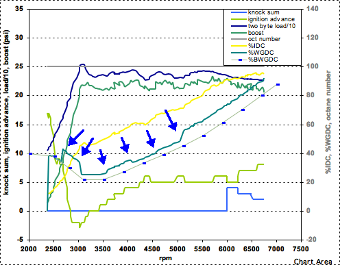
The "Max WGDC" table is poorly named. It should be called "Baseline WGDC" table. When you are cruising, the car is at 0% WGDC (at least that's what EvoScan says), and when you stomp on the gas, the ECU looks at the engine RPM, then goes to the Baseline WGDC table, reads the WGDC number, and applies that value to the BCS. At that point, the ECU then starts comparing the actual load to the target load (BDEL + boost offset) about once every 0.4 seconds. If the actual load matches the target load, then the ECU continues to follow the WGDC value (vs RPM) in the baseline WGDC table. However, if the ECU sees a discrepancy between actual and target load, then it can/will apply a correction to the WGDC. The amount of correction depends on the values in the boost error correction table. The correction is simply to raise or lower the entire Baseline WGDC curve. So after the correction is applied, the ECU follows the raised/lowered curve. It checks again 0.4 seconds later, and if necessary, raises or lowers the curve again. This is why the correction table isn't a function of RPM. The graph shows the behavior well. The blue arrows show when corrections are made, and its apparent that the ECU is simply raising/lowering the baseline WGDC curve.
Last edited by Evo_Jay; Jul 10, 2009 at 08:44 PM.
Oct 3, 2006, 02:49 PM
#5
Evolved Member
iTrader: (8)
Join Date: Apr 2003
Location: Georgia
Posts: 2,138
Likes: 0
Received 0 Likes
on
0 Posts
Nice write up, but I do have a few questions:
1) are you leaving the restrictor in the line just before the boost control solenoid
2) Does the section of hose you are removing in step 13 have a restrictor in it already?
I know there is a restrictor either in the line from the compressor or in the line running to the waste gate actuator just don't recal which.
Oct 3, 2006, 02:56 PM
#7
Originally Posted by mad_VIII
Nice write up, but I do have a few questions:
1) are you leaving the restrictor in the line just before the boost control solenoid
2) Does the section of hose you are removing in step 13 have a restrictor in it already?
I know there is a restrictor either in the line from the compressor or in the line running to the waste gate actuator just don't recal which.
1) are you leaving the restrictor in the line just before the boost control solenoid
2) Does the section of hose you are removing in step 13 have a restrictor in it already?
I know there is a restrictor either in the line from the compressor or in the line running to the waste gate actuator just don't recal which.
2) Yes
There is two restrictors, one by the turbo, one by the solenoid. I chose to replase the line, instead of taking out the factory pill and replacing with the modified pill. this way, you can go back to stock somewhat quickly.
I left the pill by the solenoid in because it smoothes the air entering the solenoid. WIthout it, its harder to control spikes.
Trending Topics
 Oct 3, 2006, 04:28 PM
#9
How steady does this method (ECUflash + WGA oriface) control boost when compared to a ball and spring MBC?
I know most of the problem with unsteady and tapering psi is from WG exhaust and DV leakage under pressure and varies due to load, air volume, gear and rpm which is beyond the control of MBC, or in this case, sol duty cycle.
I know most of the problem with unsteady and tapering psi is from WG exhaust and DV leakage under pressure and varies due to load, air volume, gear and rpm which is beyond the control of MBC, or in this case, sol duty cycle.
Oct 3, 2006, 05:19 PM
#10
The method is pretty steady. I have never used a MBC, but have seen MAP logs of them and there similar.
One thing is that you can (& might have to) mess with error correction and such if your boost isnt steady.
You can get rid of most of the taper, just like a MBC. Run wastegate duty like so (exapmle)
ROM - WG duty
3000 - 50
3500 - 50
4000 - 50
4500 - 50
5000 - 55
5500 - 55
6000 - 60
6500 - 60
7000 - 65
If you just need to run pump gas boost, I would use a one of the bigger drill bits (57&58), but you will not have the head room to run race gas boost. Using a bigger drill bit does seem a little more stable then the smaller one (not saying the smaller bits are unstable).
This mod only take 20-30 mins to do and can easily be put back.
 Oct 3, 2006, 08:29 PM
#12
Originally Posted by mchuang
my error correction is set to 0 and my boost is steady at 20psi all the way to redline.
Oct 3, 2006, 08:34 PM
#13
Originally Posted by Evo_Kid
I left the pill by the solenoid in because it smoothes the air entering the solenoid. WIthout it, its harder to control spikes.
Oct 3, 2006, 08:40 PM
#14
^^
I had the solenoid pill out a couple times and you can get rid the spike somewhat with the WG duty, but if you at like 4K-4.5K and punch it, it would still spike how I didn't want it to. I think two restrictors is the way to go. Just one of them has to be modified.
Also, I used a MAP sensor and logging stuff , not a boost gauge for testin all this. Most boost gauges are wrong, especially on the spike. (& the taper)
Last edited by Evo_Jay; Oct 3, 2006 at 08:42 PM.


