My 2.3L build, lots o pics
 Aug 29, 2006, 02:57 AM
#1
Evolving Member
Thread Starter
My 2.3L build, lots o pics
A few different people asked me to post pics of my engine build so here they are. This was my second 4G63 build. I built a 2.4l 6 bolt for my Talon about a year and a half ago. I don't claim to be a expert, infact it amazes me that i can build a engine that runs 
Here's how the whole thing started out. I was offered a awesome deal on a 03 EVO with a spun #1 rod bearing. After scrambling to find a truck and trailer the car came home on July 28th.

Engine out on the 30th. Block to the machine shop on the 31st. Notice the dirt. The car had been sitting in a machine shed since Feb 05.
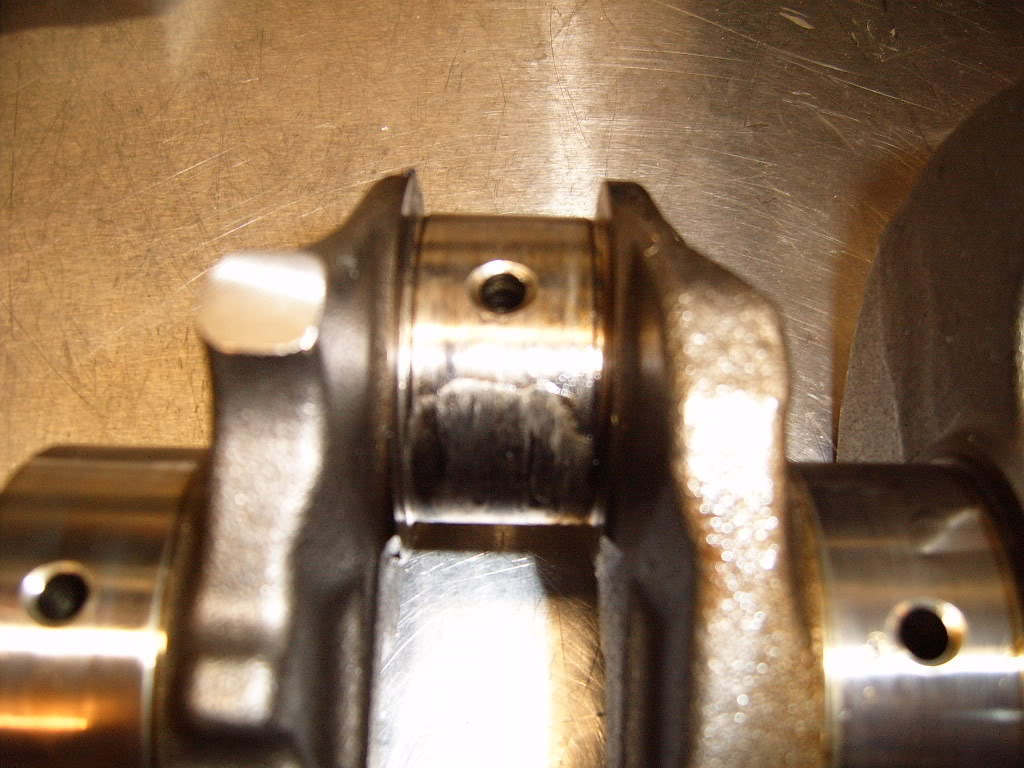
The ugly, one piece crank and rod bearing

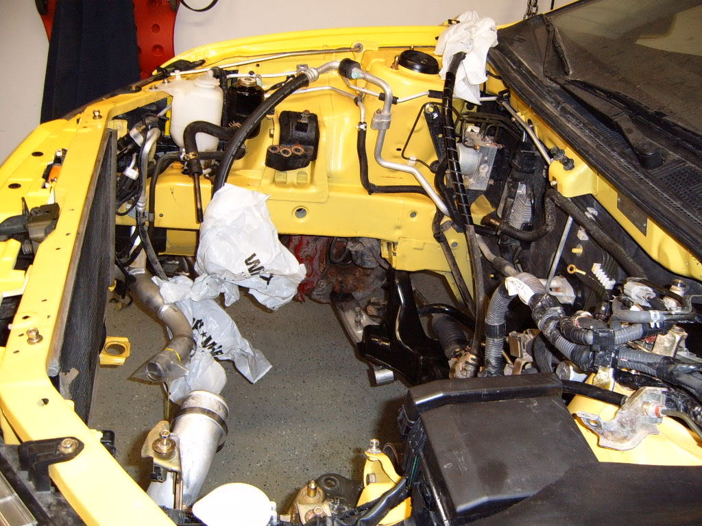
While I was waiting on parts decided to clean out the engine bay while there was no engine/trans in the way. I covered all the hoses and pipes with plastic bags to keep water from getting where it shouldn't be
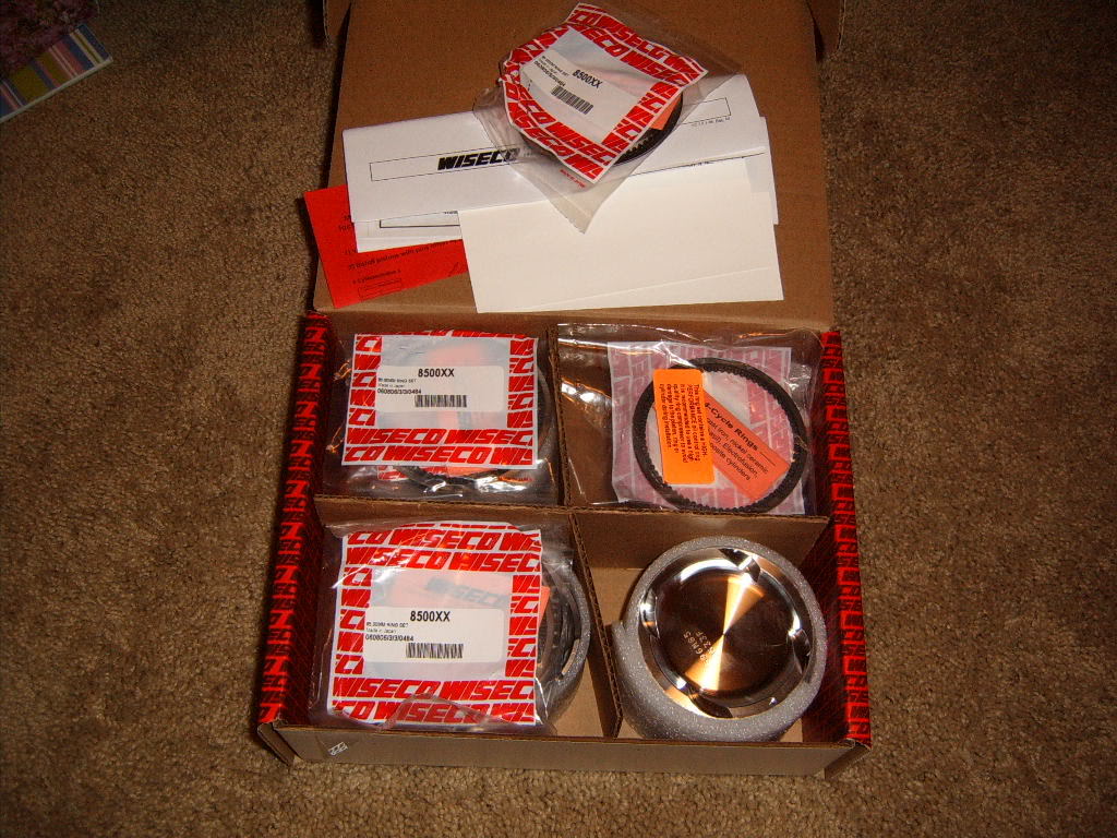
Decided to go with a stroker, if I have to rebuild a engine might as well have some fun Parts started showing up by Aug 2nd.
Block back from the machine shop on the 3rd. The bores were in pretty good shape so i had the block decked, honed and hot tanked.
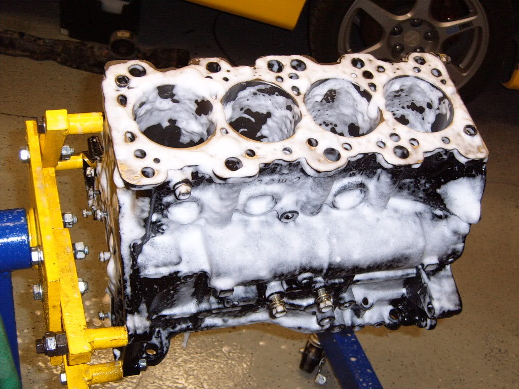
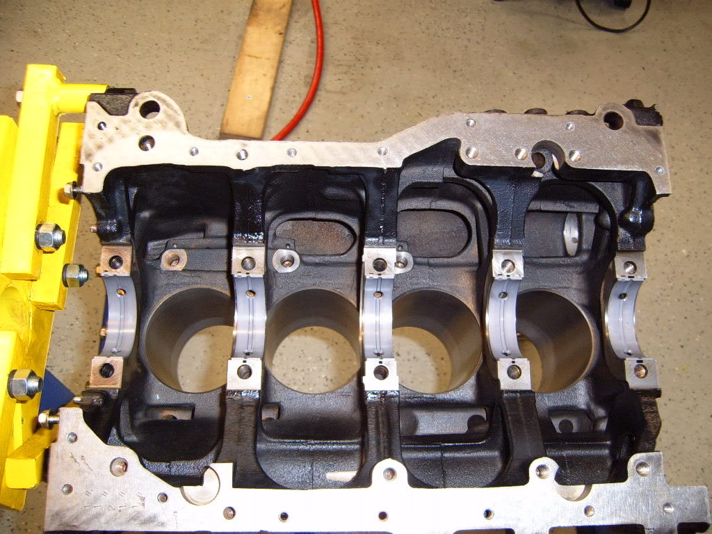
First thing to do, give the block a bath. I used foaming engine bay cleaner and simple green along with a assortment of brushes. After i cleaned the block i wiped it down with clean motor oil to prevent rust, and covered it with a bag when i wasn't working on it.
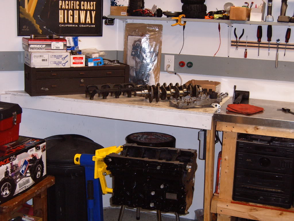
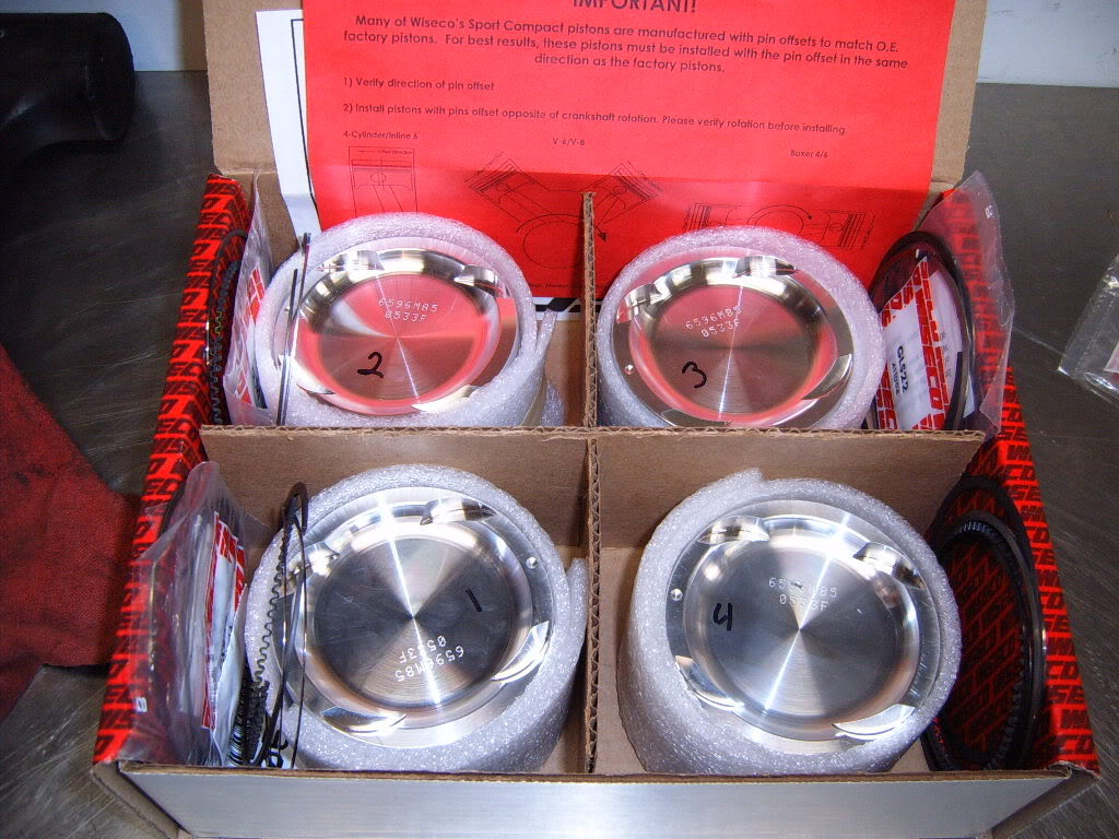
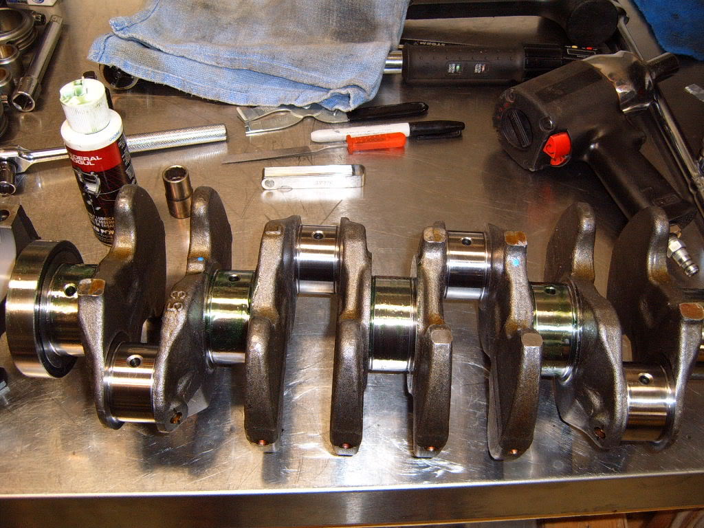
Clean block and all parts. Every things ready to go. Wiseco 8.5:1 2.3L pistons, Eagle rods, New mitsu 2.4L crank, Mitsu Engine Gasket kit, ACl bearings, and ARp head studs. Before starting I numbered all pistons and rods 1-4 so i knew what went where and to keep all my measurements strait. I also wrote the cylinder numbers on top of the block to eliminate and possibility of error.
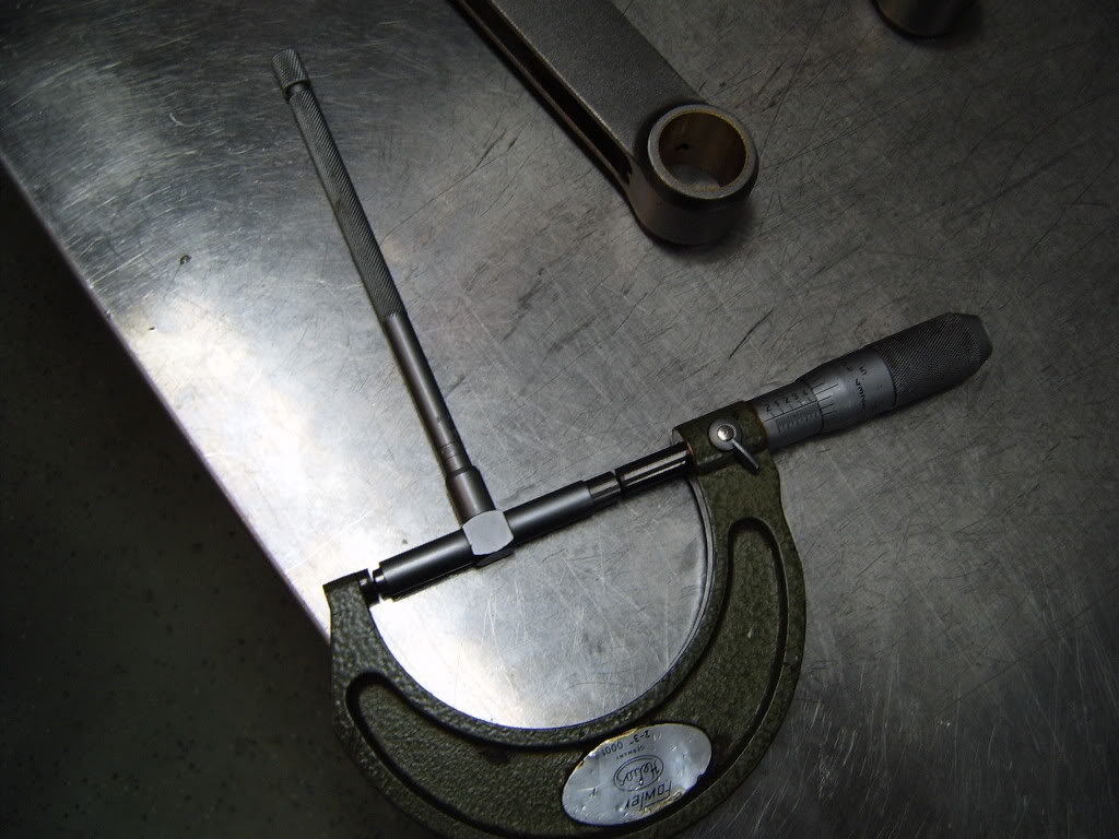
I wanted to measure all clearances. however I'm too cheap to buy a proper bore gauge (I'm a DSM'r), so I became quite good at using a snap gauge. I took at least 3 measurements of every thing and averaged them out. I also used plasti gauge, but I'll show that later. Before i measured all clearances i cleaned the surfaces to be measured with brake cleaner and clan rag.
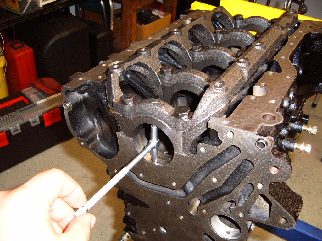
Measuring bore with snap gauge.
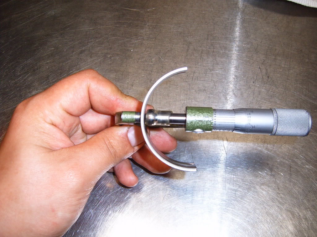
Taking measurement from snap gauge with micrometer (I'm actually measuring a snap gauge used for the crank main bore, but its the same idea).
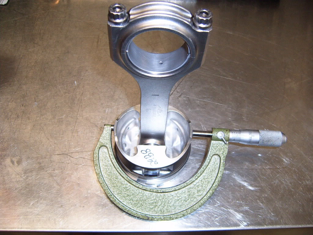
Measuring the piston Diameter with the mic. This pic is of a piston rod combo because I forgot to take a pic before I assembled the pistons and rods. Difference between the 2 measurements is the piston to wall clearance. I had numbers of .0020".
Next I bolted the crank cradle to the block and torqued to spec. So I could measure the crank main bores in the same way, as the cylinder bores.
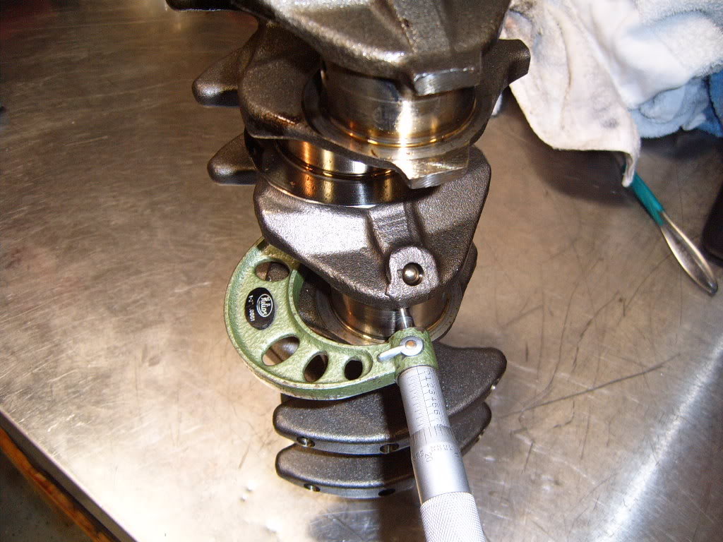
To measure the main and rod bearings i used a ball bearing and a small piece of fuel line attached to the mic so that i could get a true reading of the bearing thickness. With out the ball bearing the curve of the bearing gives a inaccurate reading, as the mic has a flat end that is unable to sit on the bearings curved surface. o get the total thickness of the bearings I multiplied the thickness by 2 since it sits on both sides of the crank.
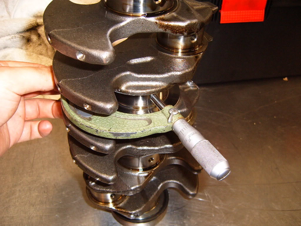
Measuring the crank main journals. The difference between the main bore and the bearing thickness X2 plus the main journals is the main bearing clearance. I got numbers rite around .0016"
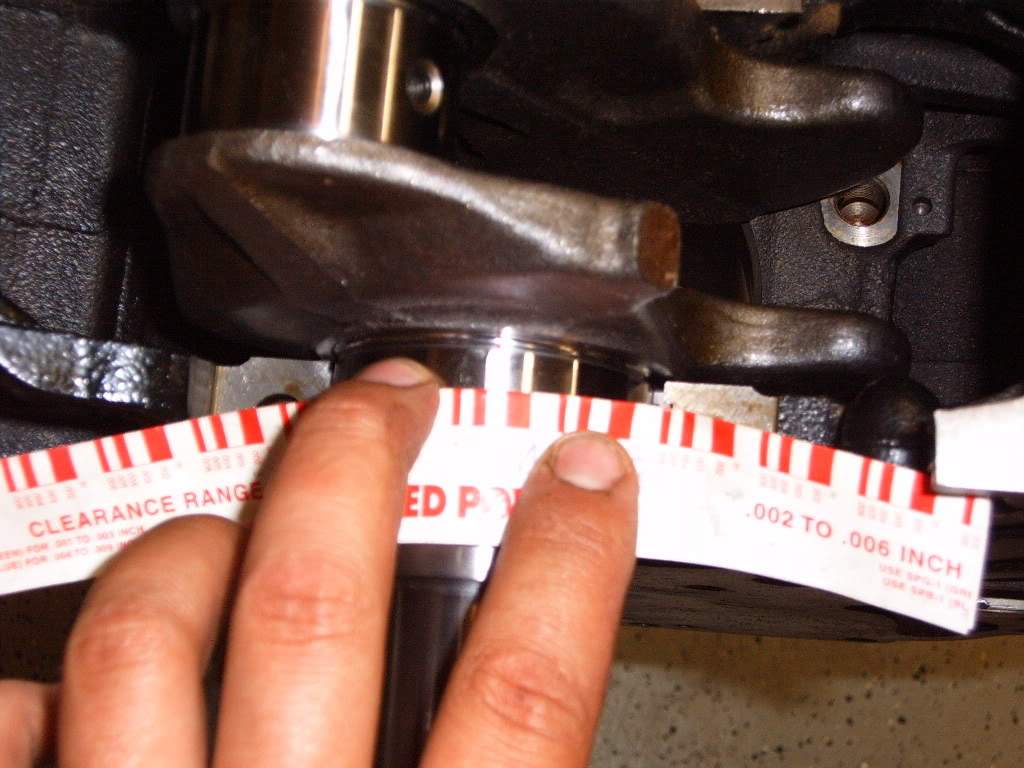
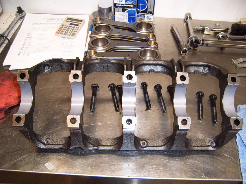
Since i wanted to plasti gauge the bearing clearances as well I removed the main bearing cradle and installed main bearings (after cleaning them), in both the block and the cradle. I then re-installed the crank. I put a piece of plasti gauge on the top of each main journal. Then re-installed the main cradle and bearings, and torqued the main bolts to spec. This compresses the plasti gauge between the crank and bearings. Once all the bolts have been torqued to spec I removed them, and the cradle. The piece of plasti gauge is now a smashed piece of wax stuck to the crank and bearing. Using the supplied measuring table with the plasti gauge I measured the clearance to get .002-.003" on all 5 bearings. This is pretty close to what i got with the snap gauge and mic, as well as what I wanted, so I was happy with that. After i was done with this I cleaned the plasti gauge off the crank and bearings with WD40 and a rag.
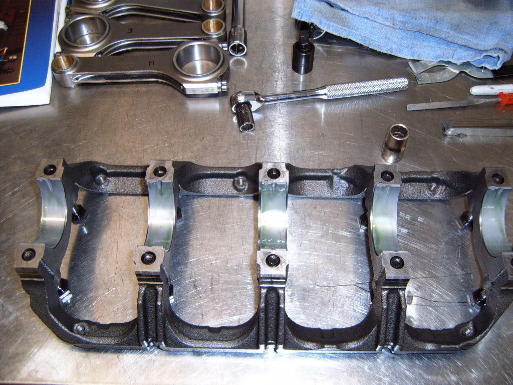
Bearings installed in block.
Cradle bolted down with plasti gauge.
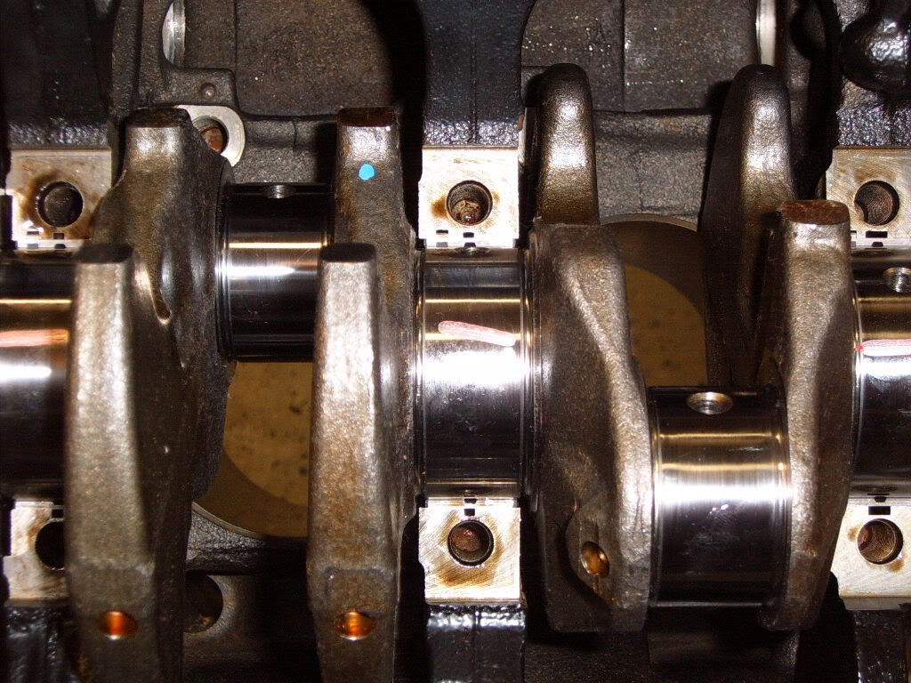
What it looks like after I removed the cradle and top bearings.
Measuring the plasti gauge.
Next i installed the crank into the block, but in hind sight I should have measured the rod to crank clearances first. It would have been much easier to do with the crank out of the block. I measured the rod bearing clearances much the same as the mains.
After bolting the rod caps on and torquing to spec I measured the bore diameter with the snap gauge, just like the main bores. Then i measured the bearing thickness the same way as the main bearings. I found my clearances just like the mains. Rod race diameter minus bearing thickness X 2 + rod journal diameter. My clearances were all about .0020", what I wanted
Measuring the rod journals, just like the mains.
Just like the mains I plasti gauged the rod bearings. Install the clean bearings in the rod and rod cap. Bolt them to the crank with a piece of plasti gauge and torque to spec. All of them showed .0020" with the plasti gauge, so I was satisfied.
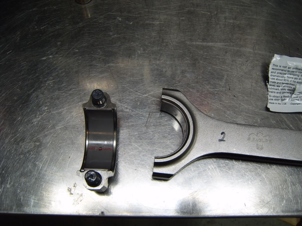
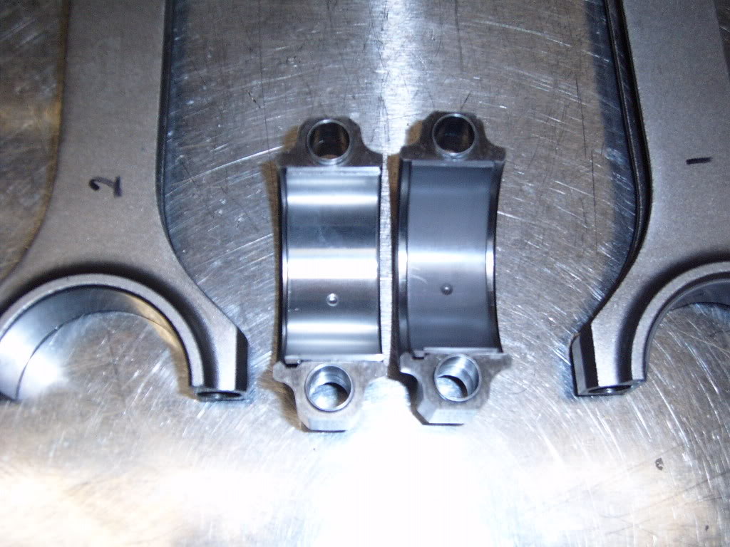
Something the got me all worked up just before i started the build was Eagle has a sticker on the inside of the rod box that says their rods are to be used with 6 bolt (89-92) rod bearings. Well by the time I saw this I had already ordered all my parts and I ordered 7 bolt rod bearings, I figured i was building a 7 bolt engine with 7 bolt bearings. So when I noticed this sticker I called all the local parts stores looking for 6 bolt bearings. NAPA got me Cleviete 77 6 bolt bearings by the next morning. After all the calling around and worrying I had the wrong bearings, it turn out the 7 bolt bearings work just fine. The 6 bolt bearings are 23.5mm wide vs. 7 bolts 21.1mm. The thickness are the same. Since i was building this engine due to a spun rod bearing I was happy about the extra 2.4mm of surface area offered by the 6 bolt bearings. However the 6 bolt bearings didn't fit in the rods . The tang is too wide for the slot in the rod, and its on the edge of the bearing, which causes the bearing to sit off center in the rod. It was recommended by another member on here to file the tang down to make it fit. But I didn't feel real comfortable doing that, and i preferred to use the coated ACL bearings vs. the Cleveites. So I ended up using the 7 bolt bearings I origionally had . This pic shows the difference between the 6 bolt (left) and 7 bolt (right) bearings.
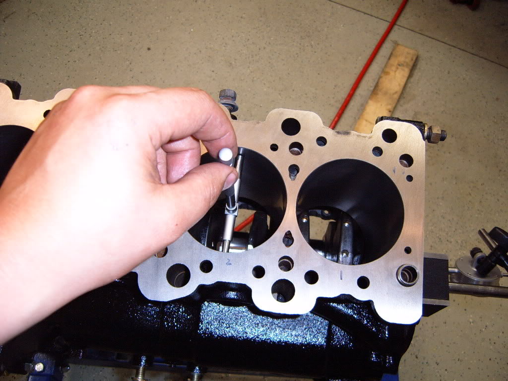
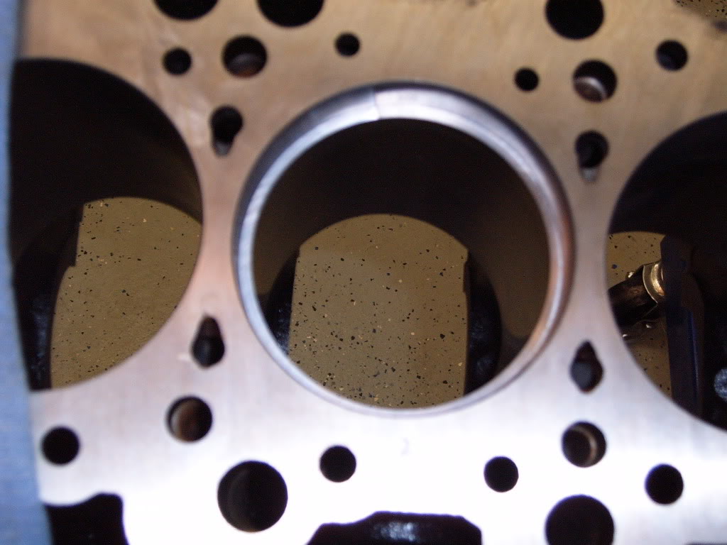
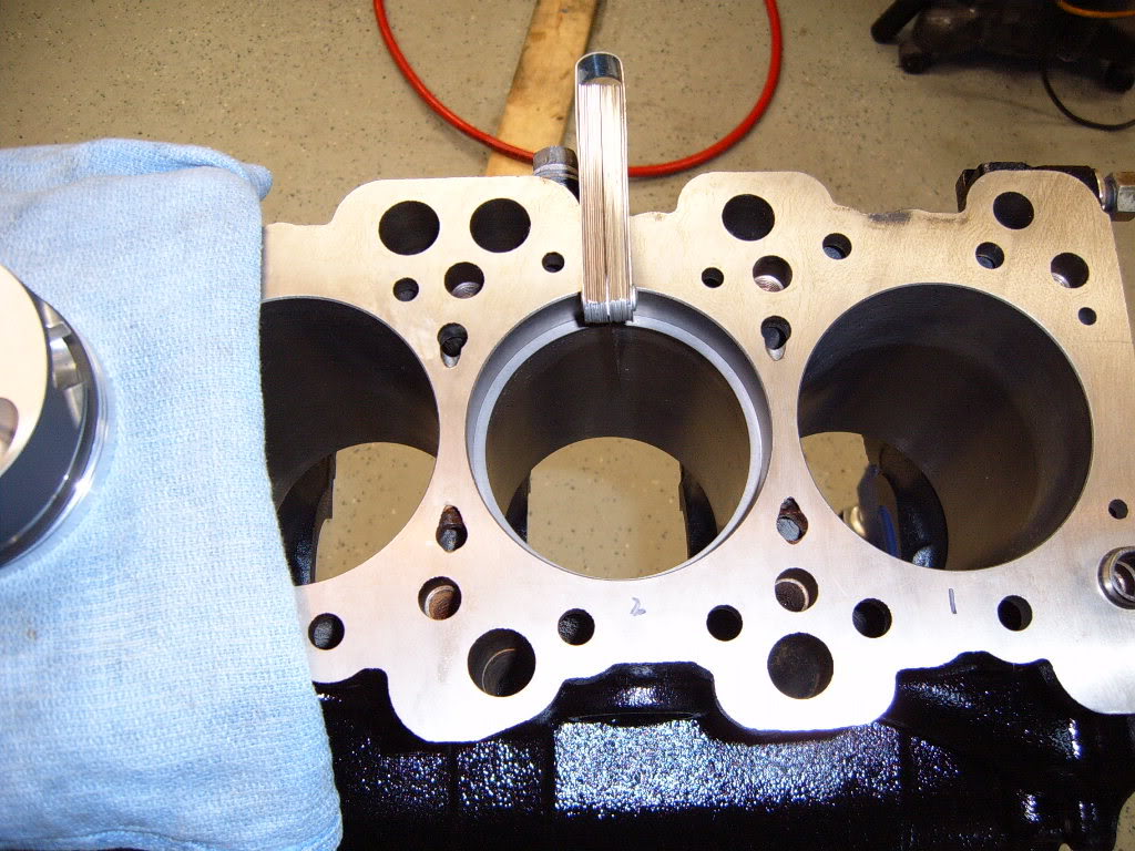
Alright next up was filing the rings. Each manufacture has different recommendations for ring gap. After talking with a few different people I decided on .017 for a top gap and .020" for the bottom ring. Wiseco's web site has a good bit of technical info about their rings and recommended gaps. I filed the rings one cylinder at a time, keeping the rings with their respective piston in the box. I filed the top rings first and the bottom second. I installed the bottom ring on one piston to use as a gauge for pushing each ring the same distance into the bore and to keep them flat in the bore. The ring sits on the top of the block and doesn't allow the piston to go any farther into the cylinder than the ring.
Here's a pic of the piston I used to seat each ring in to the cylinder.

Here's what the ring looks like in the cylinder.
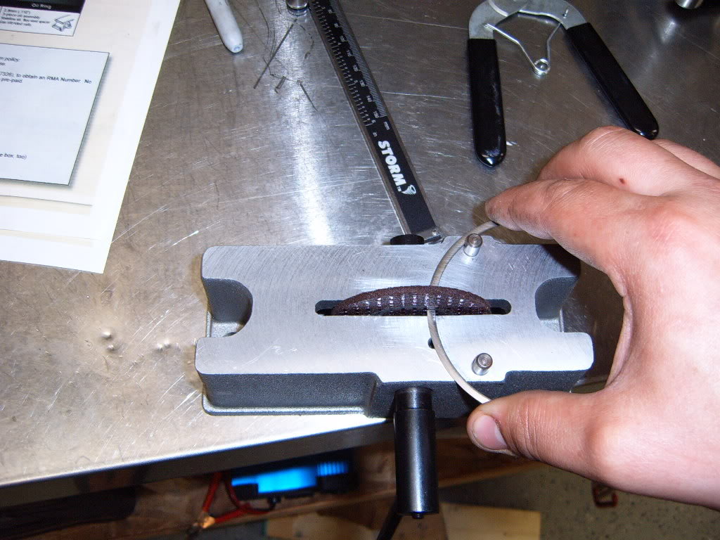
Once the ring is square in the cylinder I measured the gap with feeler gauges.
All the gaps were smaller than the .017 and .020 I was looking for so they needed filing. To file the rings i used my cheap Summit ring filer. It has worked fine for the 2 engines i have built, but I can see how a nice filer that measures the amount of material cut would speed things us. Spinning the disk so that it cut from the out side to the inside of the ring I took off a little at a time and re-checked the gap. After each time I took a little material off the ring I re-checked to make sure the ends of the ring are square with each other.
After the desired gap was reached, using a fine hand file I cleaned off any small burs left from filing the ring and put them back with their piston in the box.
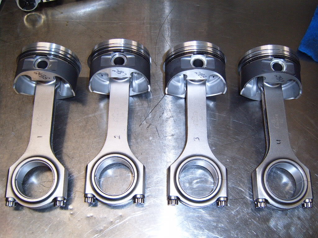
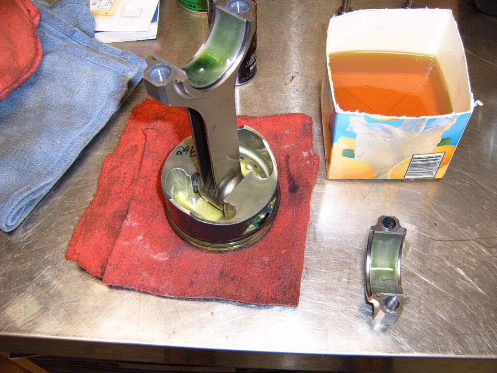
Once all the rings were filed I assembled the pistons and rods. First I installed one of the retainer clips in the piston. Then I used a little assembly lube on the wrist pins and the rods to allow the pin to slide through the piston and rod easier. After the wrist pin was in the piston rod combo I installed the second retainer clip on the other side of the piston. These little things are kinda tough to seat in their grooves, but with a little patience and a plastic screw driver handle I only had 1 go flying across the garage After installing the wrist pin in each piston rod combo I installed the rings on the piston, so I had a complete piston, rod, and ring setup. I installed the oil ring retainer first, then the lower oil ring, then the oil ring spacer and finally the top oil ring, making sure to space the gaps as Wiseco recommended. Once i had the oil ring set up installed I installed the lower ring followed by the top ring. I used a Sears ring pliers for the compression rings. This little $8 tool makes installing the rings much easier. When installing the compression rings I made sure to have the writing on the ring facing up and space the gaps according to Wisecos instructions. I didn't get any pics of me doing any of this, but its all pretty strait forward, and Wiseco has some great instructions that explain it. Here's a pic of the finished piston, rod and ring combos.
At this point I should have installed the oil squiters. I didn't, I forgot about them till I had the whole rotating assembly together . So I had to pull the cradle off and was then able to get them in and torqued to spec. Thankfully I didn't have to pull the crank and pistons.
Now it was time to install the crank. First I cleaned the block and cradle where the bearings sit really well with a clean rag and brake cleaner. Then i cleaned all the bearings with the same rag and break cleaner. I didn't want any dirt or oil between the bearing and its mating surface. Once i had everything clean I installed the bearings in the block and cradle, as well as the 2 thrust bearings.
Next I liberally applied assembly lube to all the bearing faces and the crank.
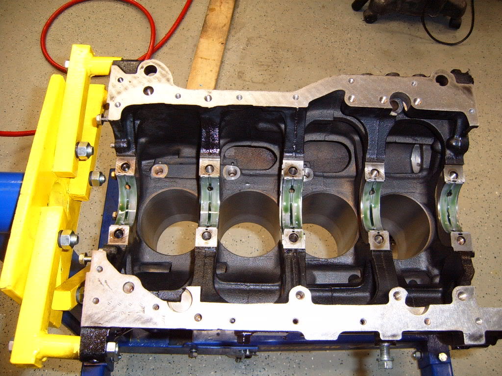
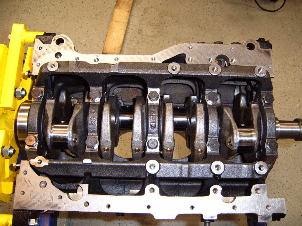
Once i had every thing lubed to satisfaction I carefully installed the crank.
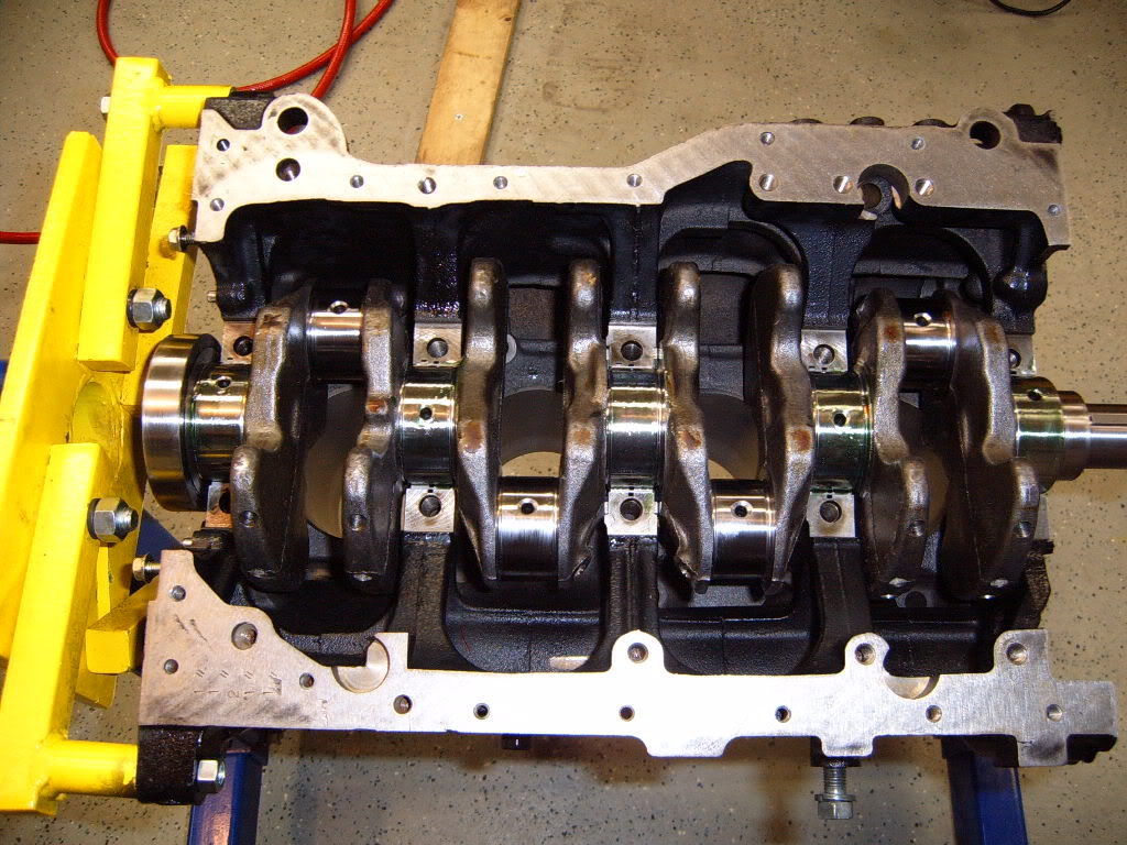
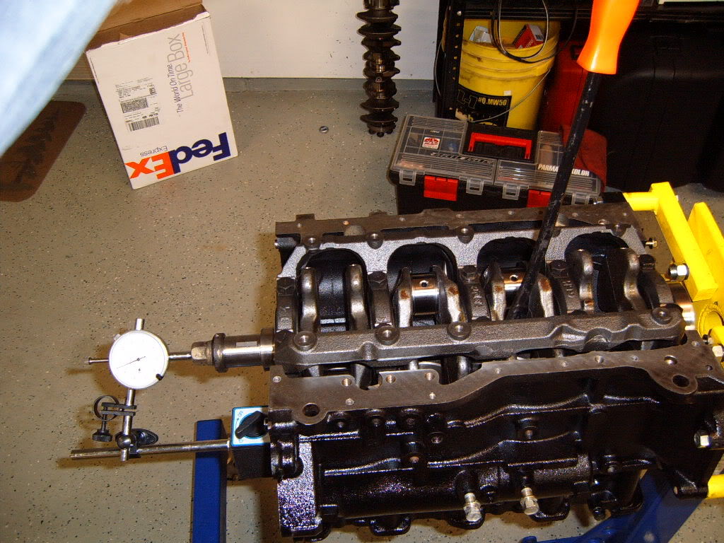
Then I installed the cradle and torqued all the main bolts to spec using 30wt motor oil and the method described in the factory service manual. Once all the bolts were torqued i checked to see if the crank would spin with little resistance. It did
Once the crank was in and the cradle all bolted down I checked the end play of the crank. I did this by attaching a dial indicator to the end of the block. Once the needle is set to zero I pried the crank each way and watched how much play was present. There was a total of .005", which is with in mitsu's factory specs. Again I was happy

Now it was time to install the pistons and rods. First i cleaned the bearing mating surfaces on the rod and rod cap, as well as the back sides of the bearings. I used a clean rag and brake cleaner, just like on the main bearings. I then inserted the bearings into the rod and cap. Before installing each piston I soaked them in new motor oil. This makes a mess, but makes it easier to slide the pistons and rings out of the ring compressor and in to the block.
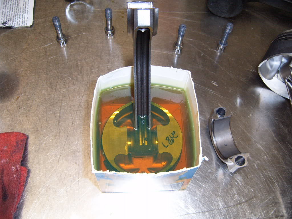
While the piston was in its oil bath I lubed the bearing surfaces and crank rod journals with assembly lube. I applied assembly lube to the cylinder walls to help lube the piston as I inserted it in to the cylinder. I also coated the ends of the rod bolts with the ARP molly lube.
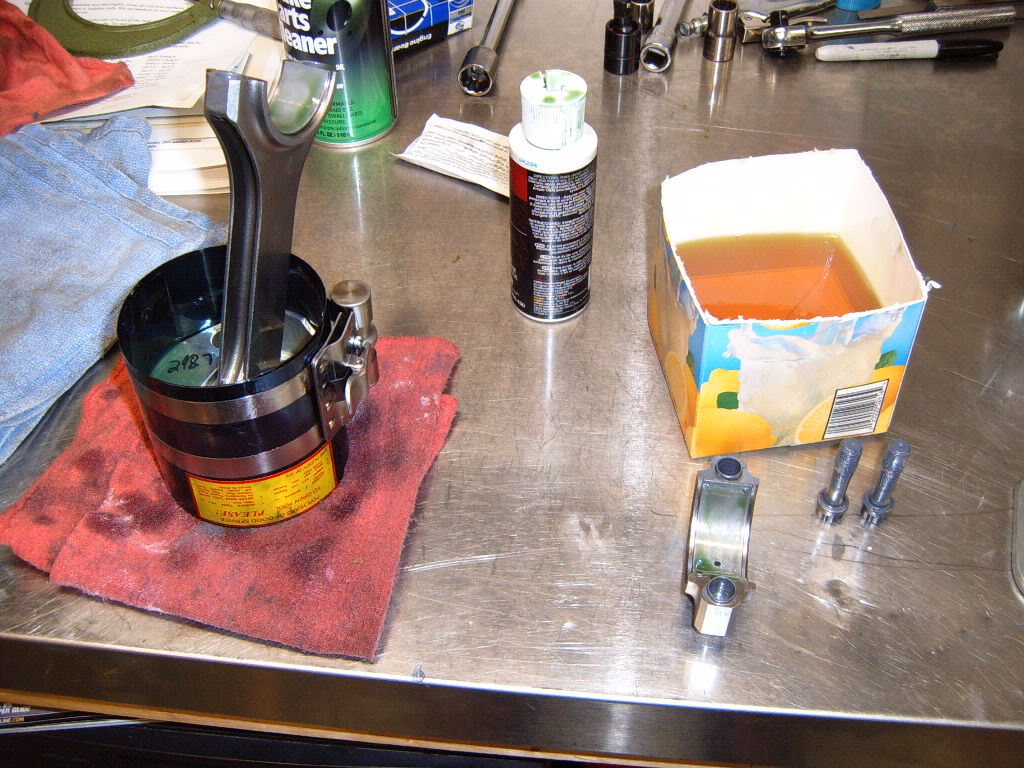
Next I pulled the piston out of the oil and put the ring compressor on it. I tightened the ring compressor till it was pretty snug.
I rotated the crank so the rod journal for the cylinder I was working on was at the bottom. I then carefully lowered the rod into the cylinder making sure the mark on the piston was facing the correct direction. Once the ring compressor was flush with the top of the block I gently tapped the piston into the cylinder with a handle of a plastic mallet.
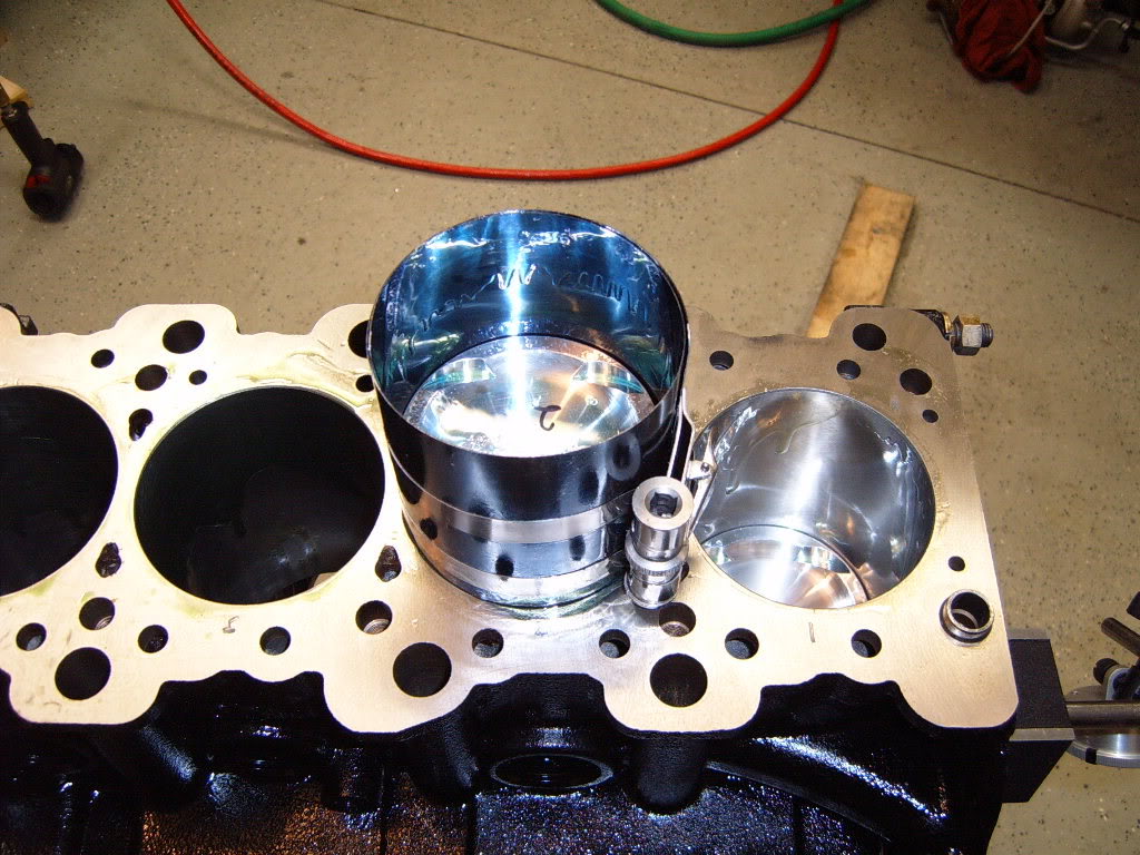
Once the piston was all the way into the cylinder I slowly pushed it down the cylinder as I guided the rod on to the crank with my other hand. Once the rod was tight with the crank I installed the rod car and tightened the bolts to spec. I repeated this procedure for all 4 cylinders taking my time and being careful not to catch a ring on the top of the block, or knick the cylinder wall with the rod.
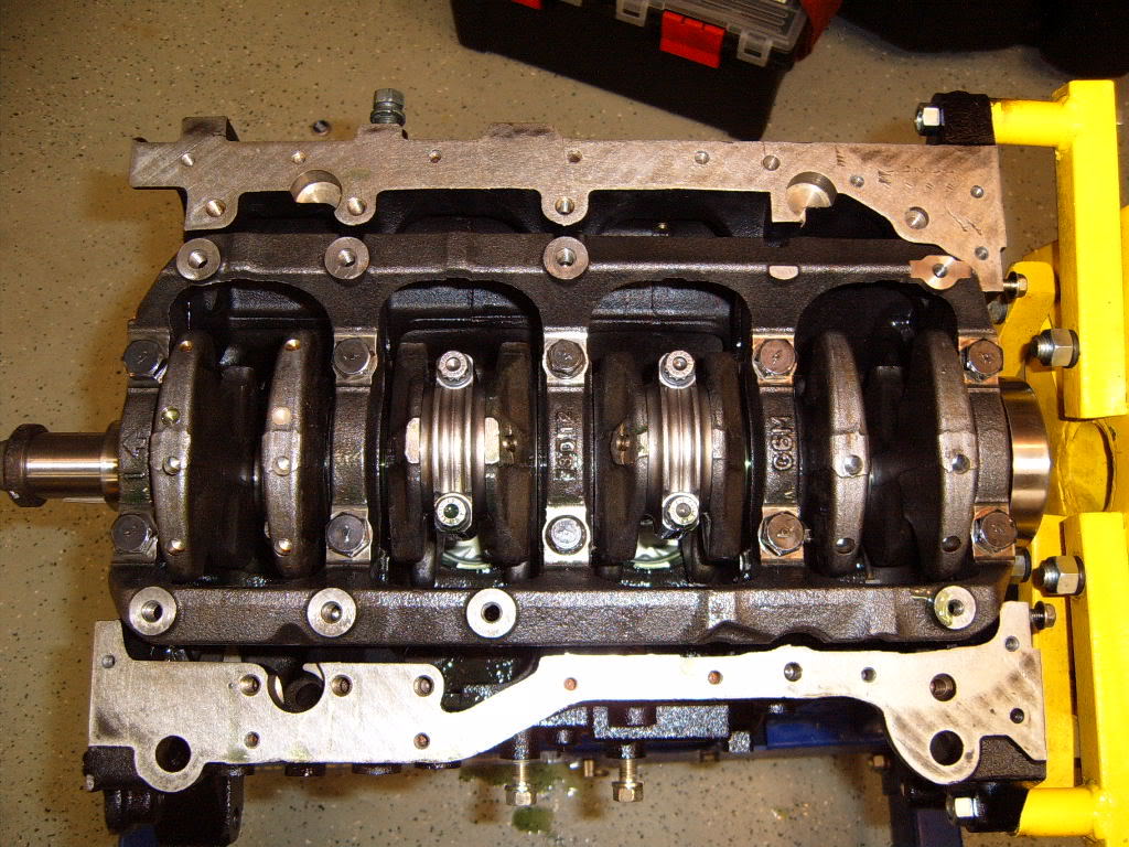
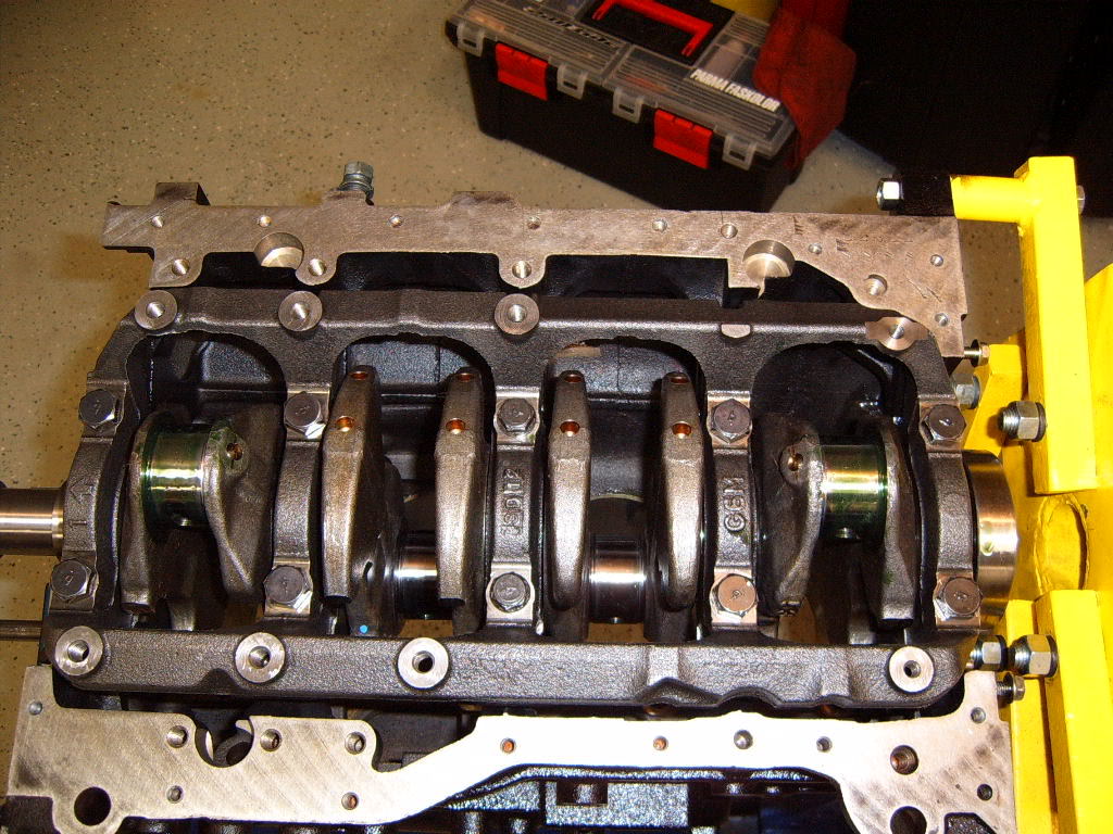
Now I had the rotating assembly all together.
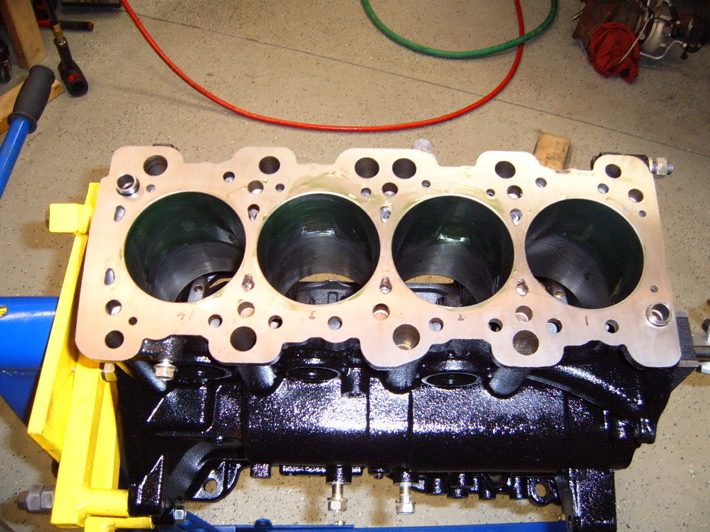
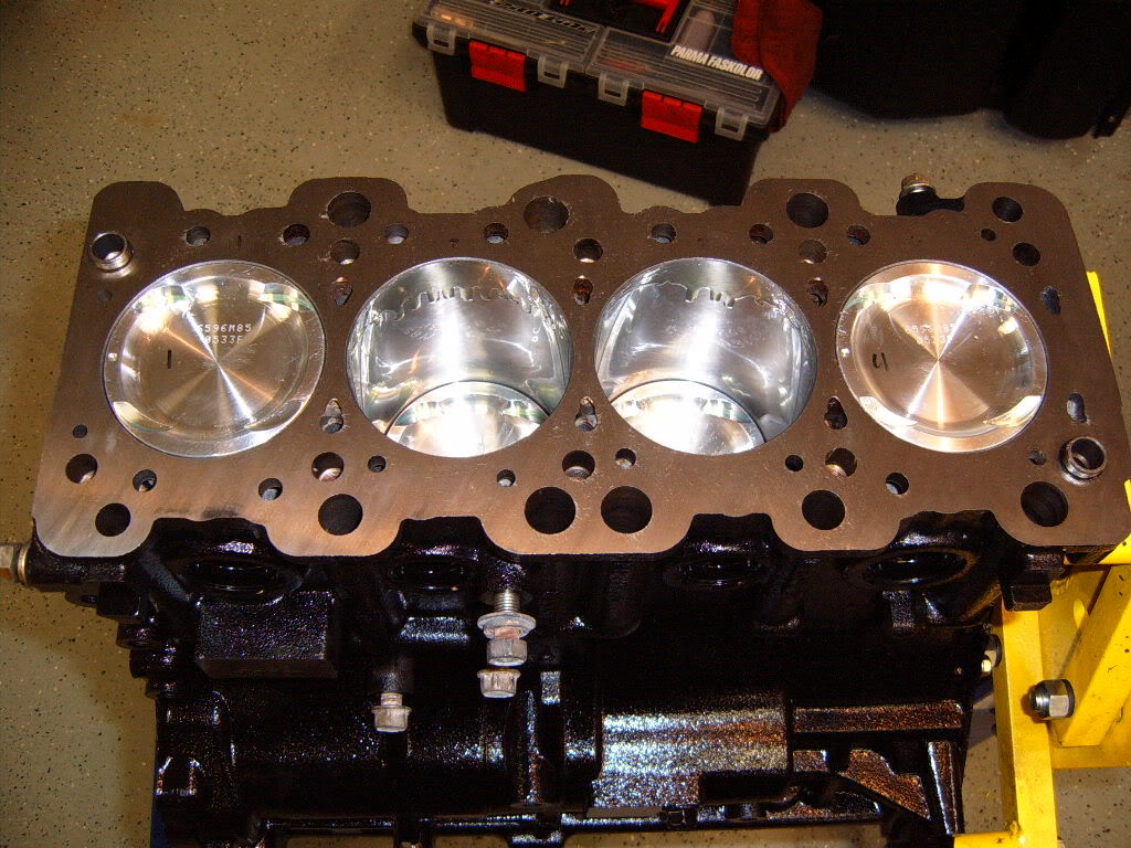
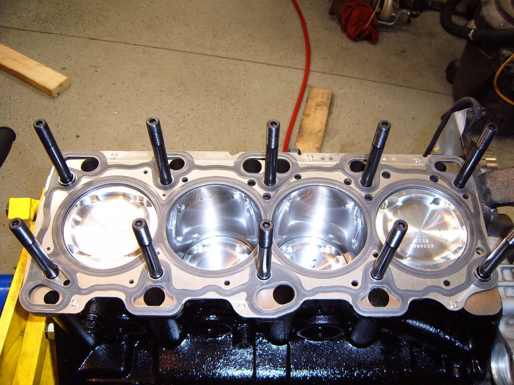
I decided to go with ARP head studs for good measure and perhaps some future boost I installed all the studs till they were snug in the block and about the same height.
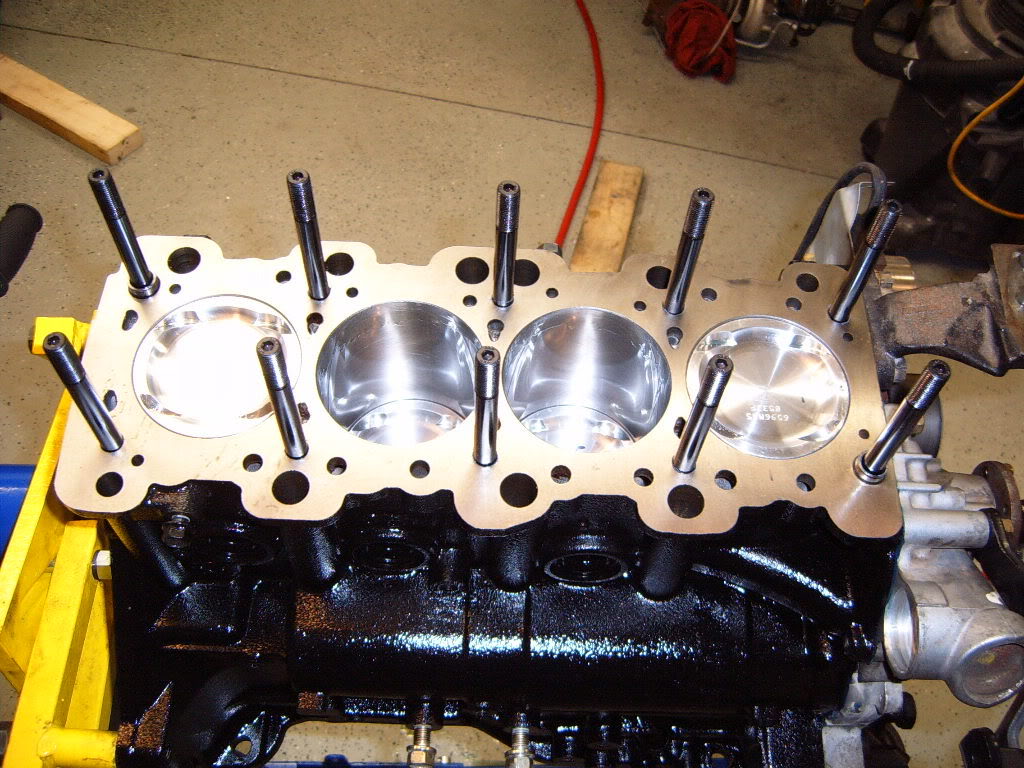
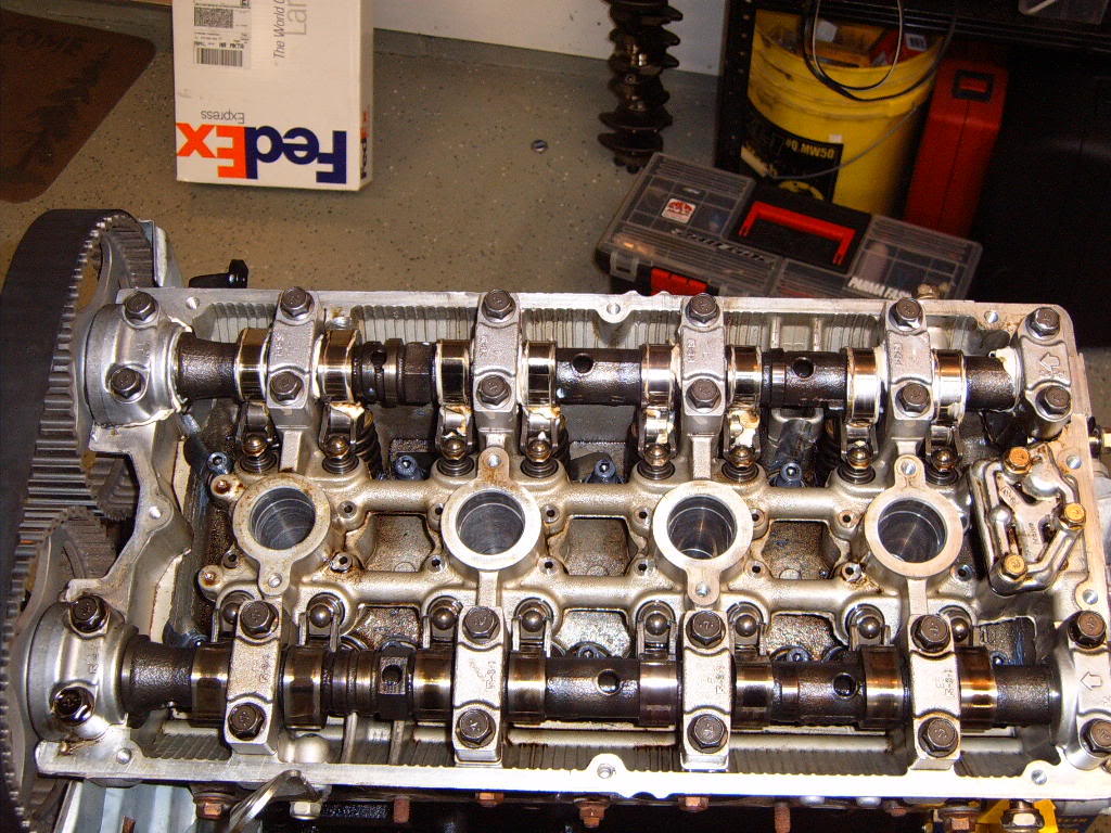
Next I cleaned the head and threw on a new mitsu head gasket.
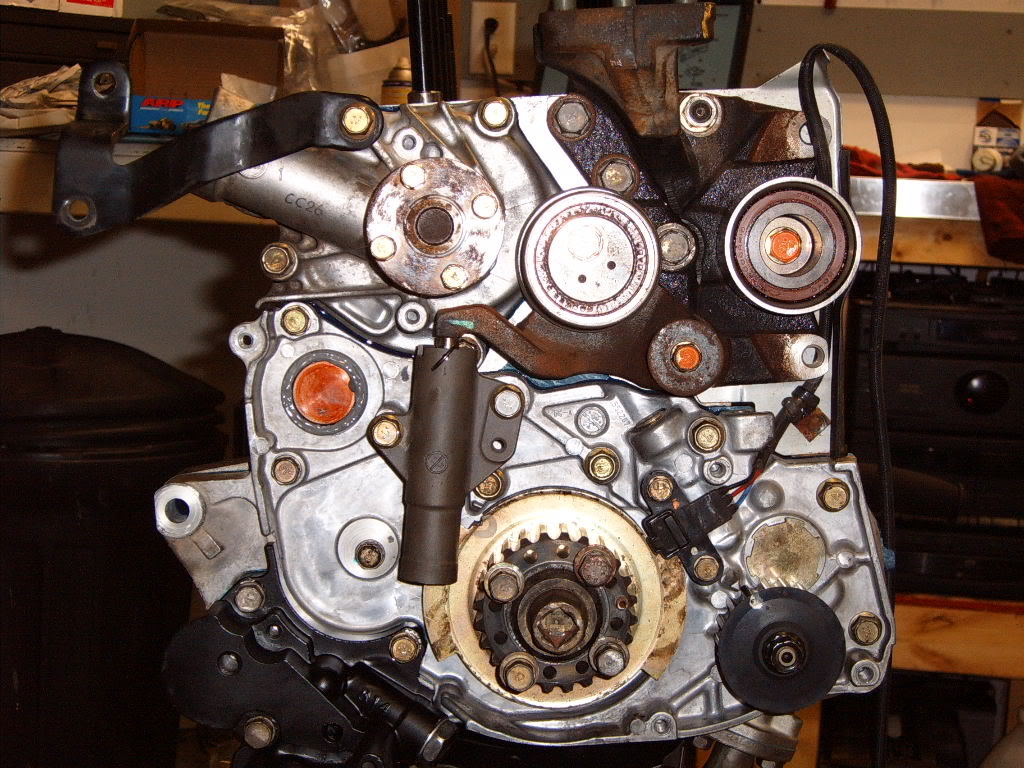
Next i bolted up the oil pump and front cover, timing belt tensioner, t belt tensioner arm, water pump, timing belt gear on the crank. Something I didn't mention earlier is that I decided to eliminate the balance shafts. I re-used the factory balance shaft bearings to block the oil holes, and I replaced the balance shaft in the oil pump cover with the stub shaft. I used the same method described in the VFAQ. I have done 6 or 7 balance shaft eliminations this way not and recommend it.
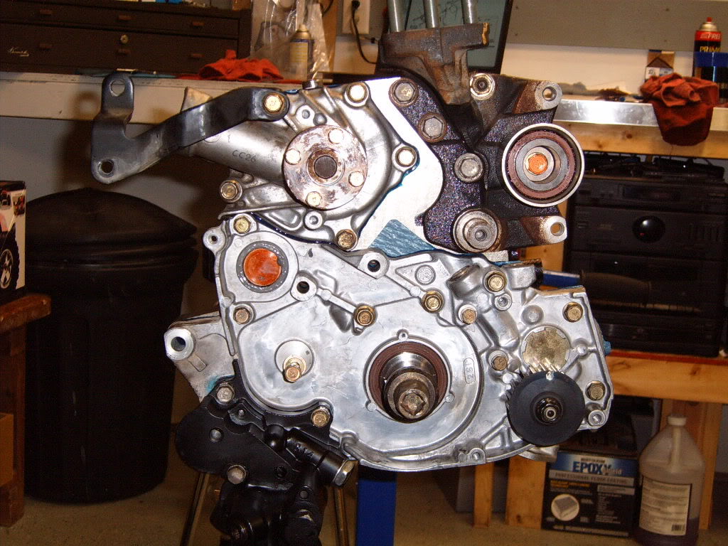
Next up was the head. After cleaning the mounting surface of the head and checking it to make sure it wasn't warped I put it on the engine and torqued the nuts to APR's recommendation using their molly lube. I used a 3 step torquing process following the factory pattern. Once i had the head on I put the timing belt on, and started bolting up all the accessories.
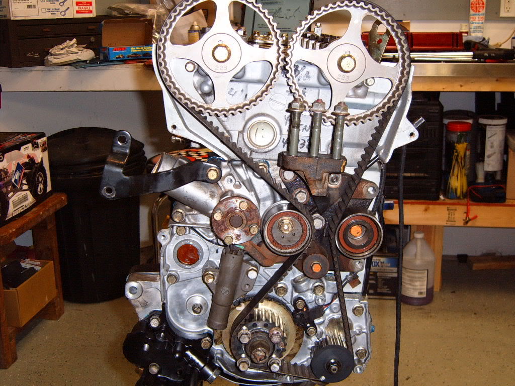
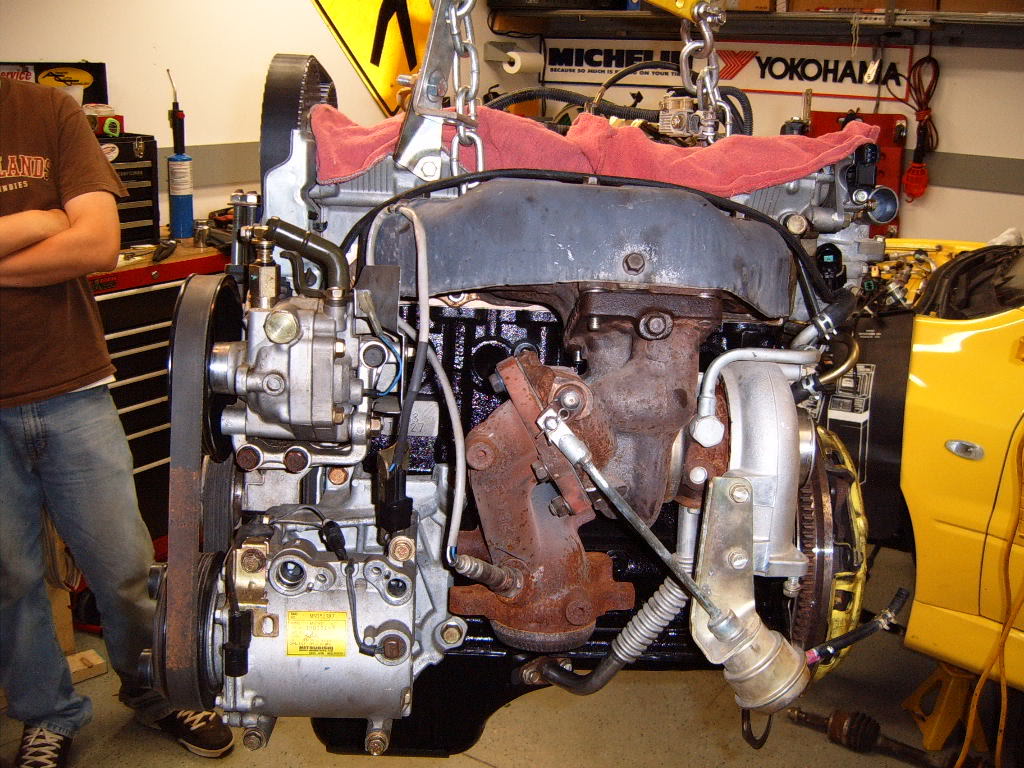
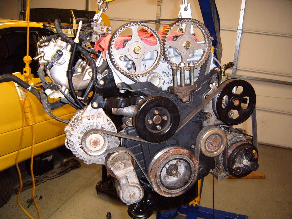
Unfortunately I could not attach the main seal and its holder with the engine on the stand, due to the bolts holding the arms on the stand. So I had to hang the engine from the hoist to put the main seal on, along with the oil pan.
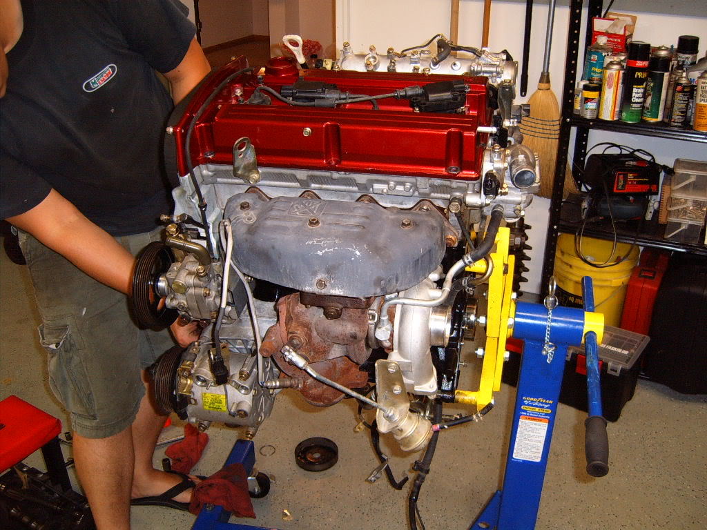
Here it is, one engine ready to go back to its home
And FINALLY its back in. I finished installing the engine exactly 2 weeks after I rolled the car into the garage.

I have only got to put about 150 miles on the engine so far. I had to wait another week to get my License Plates But now here it is, my new 2.3L EVO. 

Hope you enjoyed this, I think it took me longer to write this up than it did to build the engine.
Update 12-06-07
DYNO
Here's how the whole thing started out. I was offered a awesome deal on a 03 EVO with a spun #1 rod bearing. After scrambling to find a truck and trailer the car came home on July 28th.
Engine out on the 30th. Block to the machine shop on the 31st. Notice the dirt. The car had been sitting in a machine shed since Feb 05.
The ugly, one piece crank and rod bearing
While I was waiting on parts decided to clean out the engine bay while there was no engine/trans in the way. I covered all the hoses and pipes with plastic bags to keep water from getting where it shouldn't be
Decided to go with a stroker, if I have to rebuild a engine might as well have some fun
Parts started showing up by Aug 2nd.Block back from the machine shop on the 3rd. The bores were in pretty good shape so i had the block decked, honed and hot tanked.
First thing to do, give the block a bath. I used foaming engine bay cleaner and simple green along with a assortment of brushes. After i cleaned the block i wiped it down with clean motor oil to prevent rust, and covered it with a bag when i wasn't working on it.
Clean block and all parts. Every things ready to go. Wiseco 8.5:1 2.3L pistons, Eagle rods, New mitsu 2.4L crank, Mitsu Engine Gasket kit, ACl bearings, and ARp head studs. Before starting I numbered all pistons and rods 1-4 so i knew what went where and to keep all my measurements strait. I also wrote the cylinder numbers on top of the block to eliminate and possibility of error.
I wanted to measure all clearances. however I'm too cheap to buy a proper bore gauge (I'm a DSM'r), so I became quite good at using a snap gauge. I took at least 3 measurements of every thing and averaged them out. I also used plasti gauge, but I'll show that later. Before i measured all clearances i cleaned the surfaces to be measured with brake cleaner and clan rag.
Measuring bore with snap gauge.
Taking measurement from snap gauge with micrometer (I'm actually measuring a snap gauge used for the crank main bore, but its the same idea).
Measuring the piston Diameter with the mic. This pic is of a piston rod combo because I forgot to take a pic before I assembled the pistons and rods.
Difference between the 2 measurements is the piston to wall clearance. I had numbers of .0020".Next I bolted the crank cradle to the block and torqued to spec. So I could measure the crank main bores in the same way, as the cylinder bores.
To measure the main and rod bearings i used a ball bearing and a small piece of fuel line attached to the mic so that i could get a true reading of the bearing thickness. With out the ball bearing the curve of the bearing gives a inaccurate reading, as the mic has a flat end that is unable to sit on the bearings curved surface. o get the total thickness of the bearings I multiplied the thickness by 2 since it sits on both sides of the crank.
Measuring the crank main journals. The difference between the main bore and the bearing thickness X2 plus the main journals is the main bearing clearance. I got numbers rite around .0016"
Since i wanted to plasti gauge the bearing clearances as well I removed the main bearing cradle and installed main bearings (after cleaning them), in both the block and the cradle. I then re-installed the crank. I put a piece of plasti gauge on the top of each main journal. Then re-installed the main cradle and bearings, and torqued the main bolts to spec. This compresses the plasti gauge between the crank and bearings. Once all the bolts have been torqued to spec I removed them, and the cradle. The piece of plasti gauge is now a smashed piece of wax stuck to the crank and bearing. Using the supplied measuring table with the plasti gauge I measured the clearance to get .002-.003" on all 5 bearings. This is pretty close to what i got with the snap gauge and mic, as well as what I wanted, so I was happy with that.
After i was done with this I cleaned the plasti gauge off the crank and bearings with WD40 and a rag.Bearings installed in block.
Cradle bolted down with plasti gauge.
What it looks like after I removed the cradle and top bearings.
Measuring the plasti gauge.
Next i installed the crank into the block, but in hind sight I should have measured the rod to crank clearances first. It would have been much easier to do with the crank out of the block. I measured the rod bearing clearances much the same as the mains.
After bolting the rod caps on and torquing to spec I measured the bore diameter with the snap gauge, just like the main bores. Then i measured the bearing thickness the same way as the main bearings. I found my clearances just like the mains. Rod race diameter minus bearing thickness X 2 + rod journal diameter. My clearances were all about .0020", what I wanted
Measuring the rod journals, just like the mains.
Just like the mains I plasti gauged the rod bearings. Install the clean bearings in the rod and rod cap. Bolt them to the crank with a piece of plasti gauge and torque to spec. All of them showed .0020" with the plasti gauge, so I was satisfied.
Something the got me all worked up just before i started the build was Eagle has a sticker on the inside of the rod box that says their rods are to be used with 6 bolt (89-92) rod bearings. Well by the time I saw this I had already ordered all my parts and I ordered 7 bolt rod bearings, I figured i was building a 7 bolt engine with 7 bolt bearings. So when I noticed this sticker I called all the local parts stores looking for 6 bolt bearings. NAPA got me Cleviete 77 6 bolt bearings by the next morning. After all the calling around and worrying I had the wrong bearings, it turn out the 7 bolt bearings work just fine. The 6 bolt bearings are 23.5mm wide vs. 7 bolts 21.1mm. The thickness are the same. Since i was building this engine due to a spun rod bearing I was happy about the extra 2.4mm of surface area offered by the 6 bolt bearings. However the 6 bolt bearings didn't fit in the rods
. The tang is too wide for the slot in the rod, and its on the edge of the bearing, which causes the bearing to sit off center in the rod. It was recommended by another member on here to file the tang down to make it fit. But I didn't feel real comfortable doing that, and i preferred to use the coated ACL bearings vs. the Cleveites. So I ended up using the 7 bolt bearings I origionally had . This pic shows the difference between the 6 bolt (left) and 7 bolt (right) bearings.Alright next up was filing the rings. Each manufacture has different recommendations for ring gap. After talking with a few different people I decided on .017 for a top gap and .020" for the bottom ring. Wiseco's web site has a good bit of technical info about their rings and recommended gaps. I filed the rings one cylinder at a time, keeping the rings with their respective piston in the box. I filed the top rings first and the bottom second. I installed the bottom ring on one piston to use as a gauge for pushing each ring the same distance into the bore and to keep them flat in the bore. The ring sits on the top of the block and doesn't allow the piston to go any farther into the cylinder than the ring.
Here's a pic of the piston I used to seat each ring in to the cylinder.
Here's what the ring looks like in the cylinder.
Once the ring is square in the cylinder I measured the gap with feeler gauges.
All the gaps were smaller than the .017 and .020 I was looking for so they needed filing. To file the rings i used my cheap Summit ring filer. It has worked fine for the 2 engines i have built, but I can see how a nice filer that measures the amount of material cut would speed things us. Spinning the disk so that it cut from the out side to the inside of the ring I took off a little at a time and re-checked the gap. After each time I took a little material off the ring I re-checked to make sure the ends of the ring are square with each other.
After the desired gap was reached, using a fine hand file I cleaned off any small burs left from filing the ring and put them back with their piston in the box.
Once all the rings were filed I assembled the pistons and rods. First I installed one of the retainer clips in the piston. Then I used a little assembly lube on the wrist pins and the rods to allow the pin to slide through the piston and rod easier. After the wrist pin was in the piston rod combo I installed the second retainer clip on the other side of the piston. These little things are kinda tough to seat in their grooves, but with a little patience and a plastic screw driver handle I only had 1 go flying across the garage
After installing the wrist pin in each piston rod combo I installed the rings on the piston, so I had a complete piston, rod, and ring setup. I installed the oil ring retainer first, then the lower oil ring, then the oil ring spacer and finally the top oil ring, making sure to space the gaps as Wiseco recommended. Once i had the oil ring set up installed I installed the lower ring followed by the top ring. I used a Sears ring pliers for the compression rings. This little $8 tool makes installing the rings much easier. When installing the compression rings I made sure to have the writing on the ring facing up and space the gaps according to Wisecos instructions. I didn't get any pics of me doing any of this, but its all pretty strait forward, and Wiseco has some great instructions that explain it. Here's a pic of the finished piston, rod and ring combos.At this point I should have installed the oil squiters. I didn't, I forgot about them till I had the whole rotating assembly together
. So I had to pull the cradle off and was then able to get them in and torqued to spec. Thankfully I didn't have to pull the crank and pistons. Now it was time to install the crank. First I cleaned the block and cradle where the bearings sit really well with a clean rag and brake cleaner. Then i cleaned all the bearings with the same rag and break cleaner. I didn't want any dirt or oil between the bearing and its mating surface. Once i had everything clean I installed the bearings in the block and cradle, as well as the 2 thrust bearings.
Next I liberally applied assembly lube to all the bearing faces and the crank.
Once i had every thing lubed to satisfaction
I carefully installed the crank.Then I installed the cradle and torqued all the main bolts to spec using 30wt motor oil and the method described in the factory service manual. Once all the bolts were torqued i checked to see if the crank would spin with little resistance. It did
Once the crank was in and the cradle all bolted down I checked the end play of the crank. I did this by attaching a dial indicator to the end of the block. Once the needle is set to zero I pried the crank each way and watched how much play was present. There was a total of .005", which is with in mitsu's factory specs. Again I was happy
Now it was time to install the pistons and rods. First i cleaned the bearing mating surfaces on the rod and rod cap, as well as the back sides of the bearings. I used a clean rag and brake cleaner, just like on the main bearings. I then inserted the bearings into the rod and cap. Before installing each piston I soaked them in new motor oil. This makes a mess, but makes it easier to slide the pistons and rings out of the ring compressor and in to the block.
While the piston was in its oil bath
I lubed the bearing surfaces and crank rod journals with assembly lube. I applied assembly lube to the cylinder walls to help lube the piston as I inserted it in to the cylinder. I also coated the ends of the rod bolts with the ARP molly lube.Next I pulled the piston out of the oil and put the ring compressor on it. I tightened the ring compressor till it was pretty snug.
I rotated the crank so the rod journal for the cylinder I was working on was at the bottom. I then carefully lowered the rod into the cylinder making sure the mark on the piston was facing the correct direction. Once the ring compressor was flush with the top of the block I gently tapped the piston into the cylinder with a handle of a plastic mallet.
Once the piston was all the way into the cylinder I slowly pushed it down the cylinder as I guided the rod on to the crank with my other hand. Once the rod was tight with the crank I installed the rod car and tightened the bolts to spec. I repeated this procedure for all 4 cylinders taking my time and being careful not to catch a ring on the top of the block, or knick the cylinder wall with the rod.
Now I had the rotating assembly all together.
I decided to go with ARP head studs for good measure and perhaps some future boost
I installed all the studs till they were snug in the block and about the same height.Next I cleaned the head and threw on a new mitsu head gasket.
Next i bolted up the oil pump and front cover, timing belt tensioner, t belt tensioner arm, water pump, timing belt gear on the crank. Something I didn't mention earlier is that I decided to eliminate the balance shafts. I re-used the factory balance shaft bearings to block the oil holes, and I replaced the balance shaft in the oil pump cover with the stub shaft. I used the same method described in the VFAQ. I have done 6 or 7 balance shaft eliminations this way not and recommend it.
Next up was the head. After cleaning the mounting surface of the head and checking it to make sure it wasn't warped I put it on the engine and torqued the nuts to APR's recommendation using their molly lube. I used a 3 step torquing process following the factory pattern. Once i had the head on I put the timing belt on, and started bolting up all the accessories.
Unfortunately I could not attach the main seal and its holder with the engine on the stand, due to the bolts holding the arms on the stand. So I had to hang the engine from the hoist to put the main seal on, along with the oil pan.
Here it is, one engine ready to go back to its home
And FINALLY its back in. I finished installing the engine exactly 2 weeks after I rolled the car into the garage.
I have only got to put about 150 miles on the engine so far. I had to wait another week to get my License Plates
But now here it is, my new 2.3L EVO. Hope you enjoyed this, I think it took me longer to write this up than it did to build the engine.
Update 12-06-07
DYNO
Last edited by 9GUY9; Jan 25, 2008 at 10:17 PM.

The following users liked this post:
Jahtoot (Oct 18, 2023)

 Aug 29, 2006, 03:42 AM
#5

Nice build man!! One more thing I would have done though or what I normally do on my motors is take the rods and have them all weighed and if the difference in weight is a lot I have the machineshop make them very close to equal weight. They only shave off weight from certain spots though.

Trending Topics
Aug 29, 2006, 06:45 AM
#10
Evolving Member
iTrader: (7)
Join Date: Dec 2003
Location: Orlando
Posts: 193
Likes: 0
Received 0 Likes
on
0 Posts
First off great write up and pics. Quick question, are you getting a significant increase in vibration from 4k rpm on up? I have pretty much a similar build, but I have some vibration and I am wondering if its due to the balance shaft elimination. I know you are not really getting on it or anything yet.
 This should be stickied.
  Aug 29, 2006, 06:49 AM
#12
Evolving Member
iTrader: (1)

Join Date: Mar 2006
Location: Minnesota
Posts: 158
Likes: 0
Received 0 Likes
on
0 Posts
Hmm...... a 2.3 in MN-that's what that car needed and you did it up! Sweet deal. Hopefully I'll be right behind ya on that 2.3 soon. When's the big turbo going on?
Aug 29, 2006, 07:08 AM
#14
Evolving Member
iTrader: (8)
Join Date: Sep 2004
Location: IA
Posts: 243
Likes: 0
Received 0 Likes
on
0 Posts
damn d00d ...nice. wish i had that ability/knowledge. one day hopefully. lol
...and if you ever see a white evo with cali plates up there, its me and im prolly visiting friends.
...and if you ever see a white evo with cali plates up there, its me and im prolly visiting friends.


